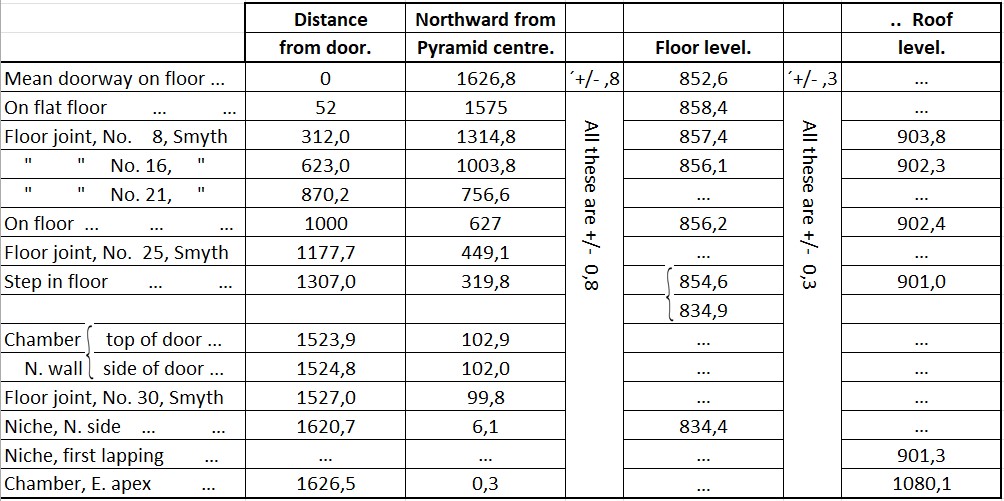
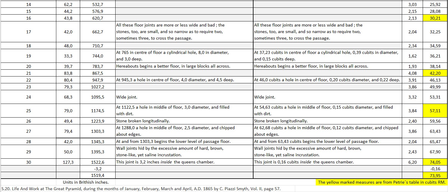
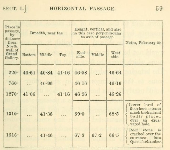
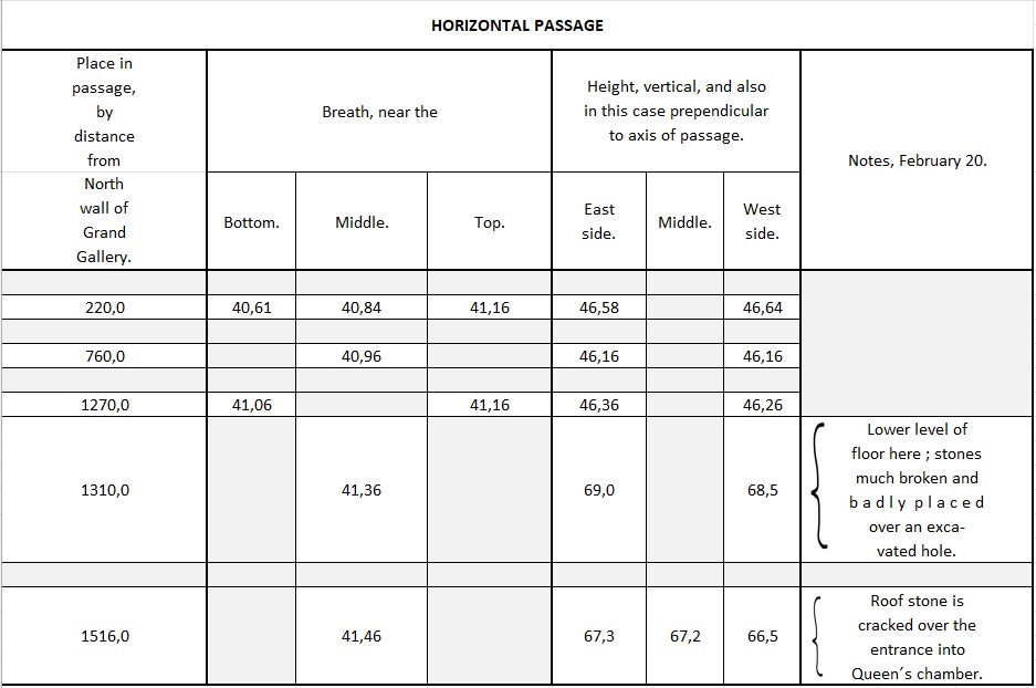
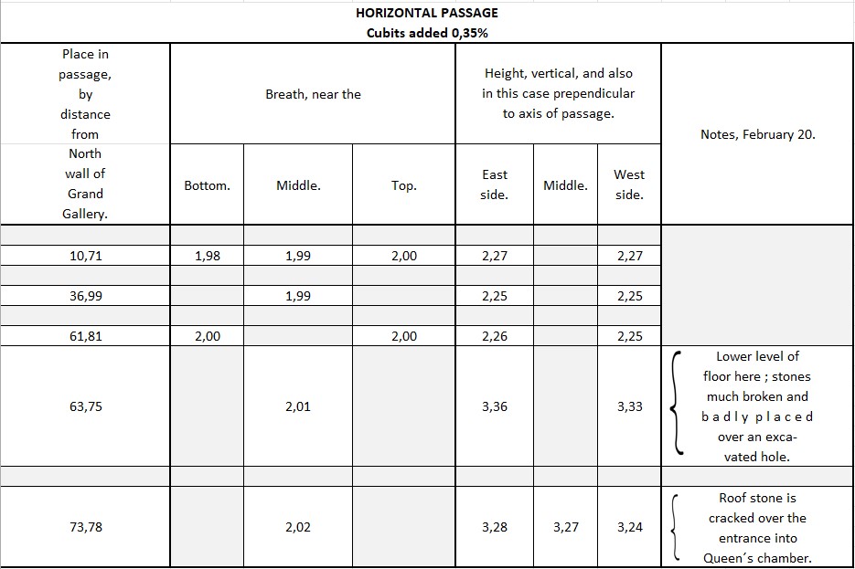
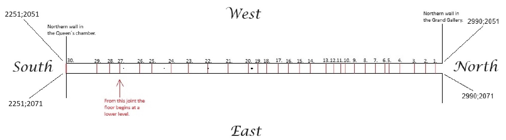
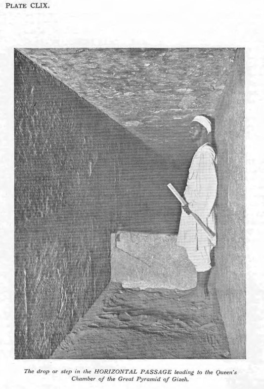
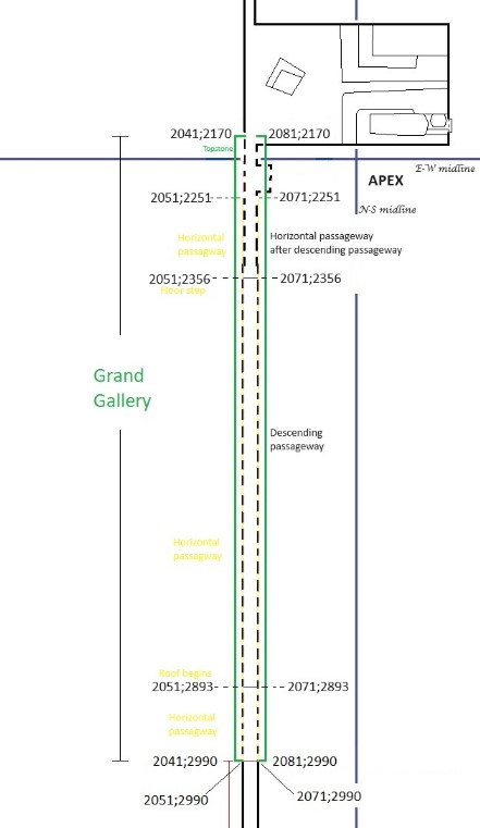
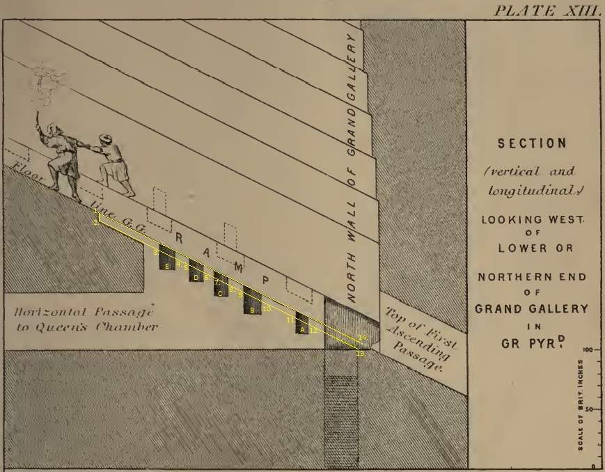
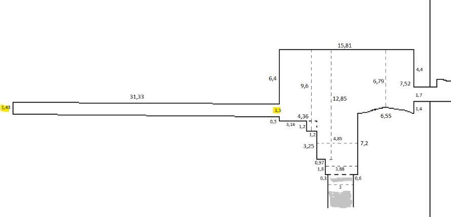
According to section 5.7.20 Petrie measured the levels of the roof and the floor of the passageway and both descend from north to south until the step near the Queen´s chamber.
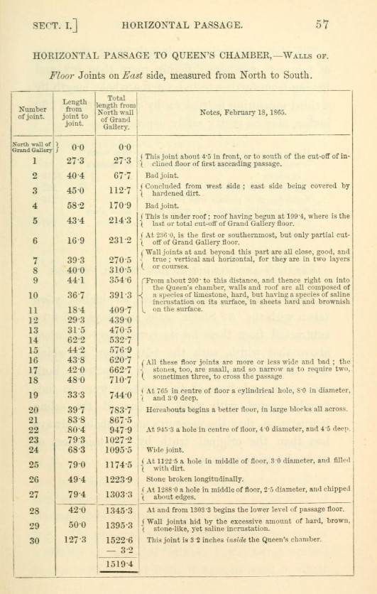
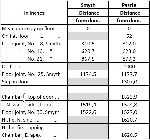
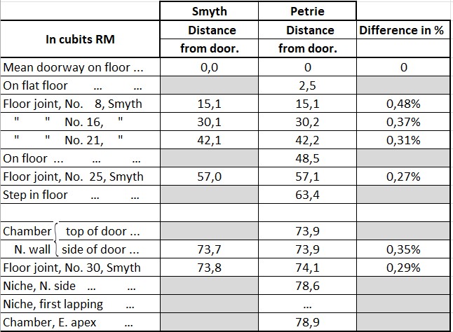
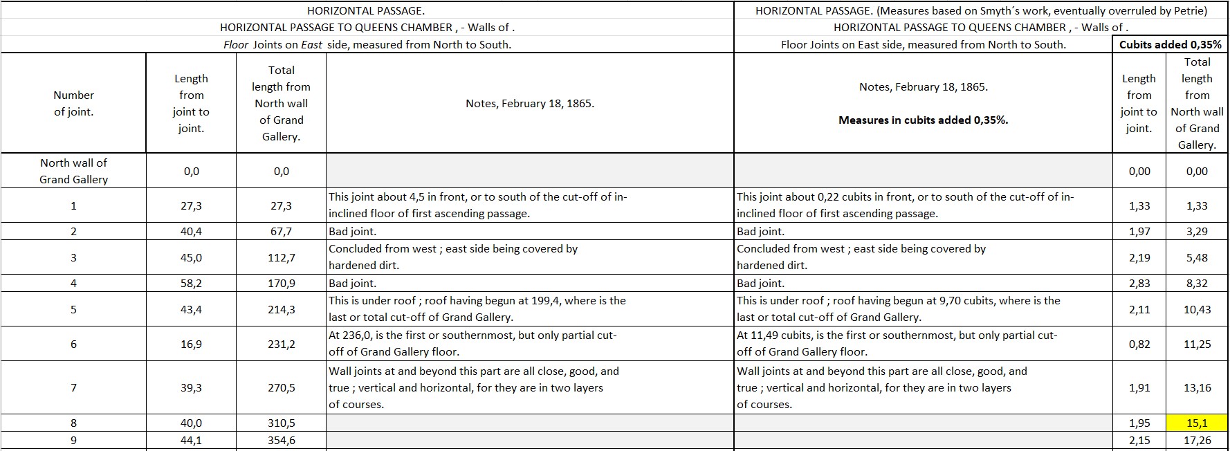
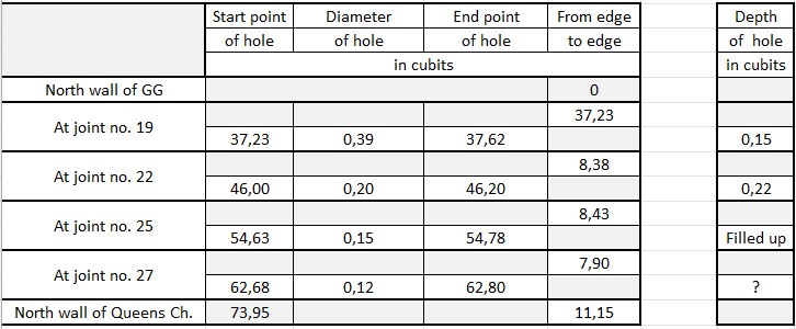
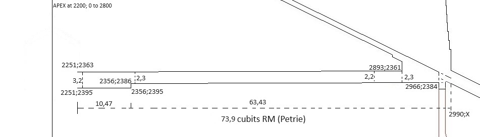
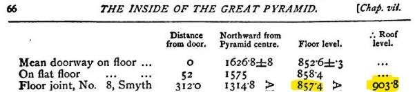
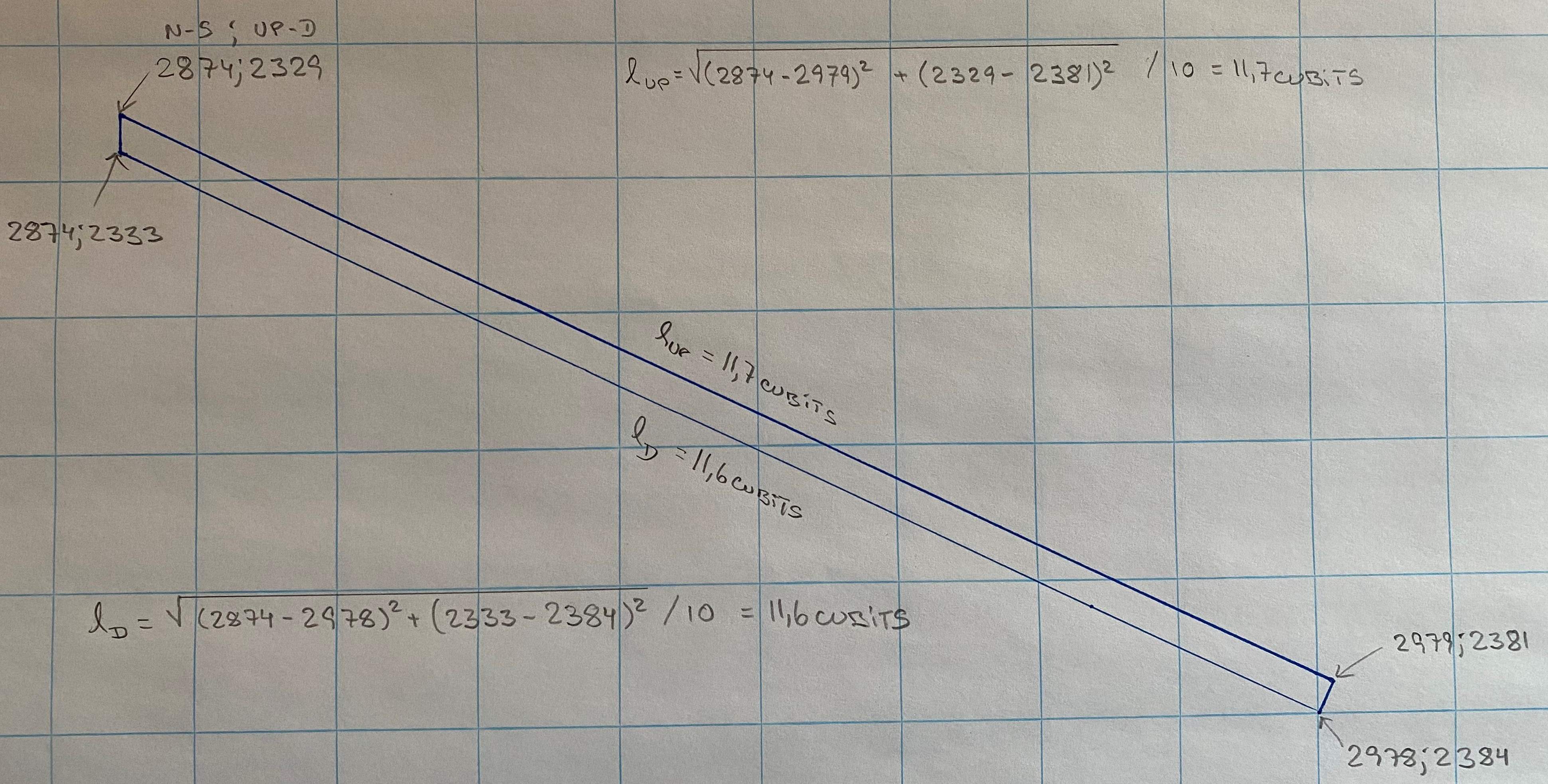
1a. At the floor joint, no. 8, Smyth, the floor level at the distance 15,13 cubits RM from the door (or northern wall) is 41,58 cubits RM equal to 416 pixels. the total height of the pyramid is 280 cubits NM equal to 2800 pixels. The coordinate for the level of the floor at that point is 2800 - 416 =2384.
1b.
At the floor joint, no. 8, Smyth, the roof level at the distance 15,13 cubits RM from the door (or northern wall) is 43,83 cubits RM equal to 438 pixels. the total height of the pyramid is 280 cubits NM equal to 2800 pixels. The coordinate for the level of the floor at that point is 2800 - 438 =2362, which is 0,1 cubits (or 1 pixel) less the roof level where the roof begins. The height of the passageway at the floor joint no. 8 is decreased to (2384 - 2362) / 10 = 2,2 cubits.
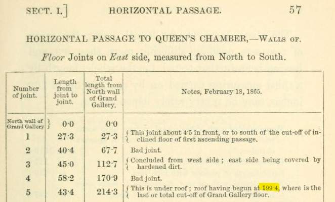
2a. At the step in the floor, at the distance 63,39 cubits RM from the door (or northern wall), the floor level is 41,40 cubits RM equal to 414 pixels. the total height of the pyramid is 280 cubits NM equal to 2800 pixels. The coordinate for the level of the floor at that point is 2800 - 414 =2386.
2b.
At the step in the floor, at the distance 63,39 cubits RM from the door (or northern wall), the roof level is 43,70 cubits RM equal to 437 pixels. the total height of the pyramid is 280 cubits NM equal to 2800 pixels. The coordinate for the level of the floor at that point is 2800 - 437 =2363, which is 0,2 cubits (or 2 pixels) less the roof level where the roof begins. The height of the passageway at the step in the floor, just before the step
is increased to (2386 - 2363) / 10 = 2,3 cubits.
3a. At the step in the floor, at the distance 63,43 cubits from the door (or northern wall), the floor level decrease to 40,50 cubits RM equal to 405 pixels. the total height of the pyramid is 280 cubits NM equal to 2800 pixels. The coordinate for the level of the floor at that point is 2800 - 405 =2395.
3b.
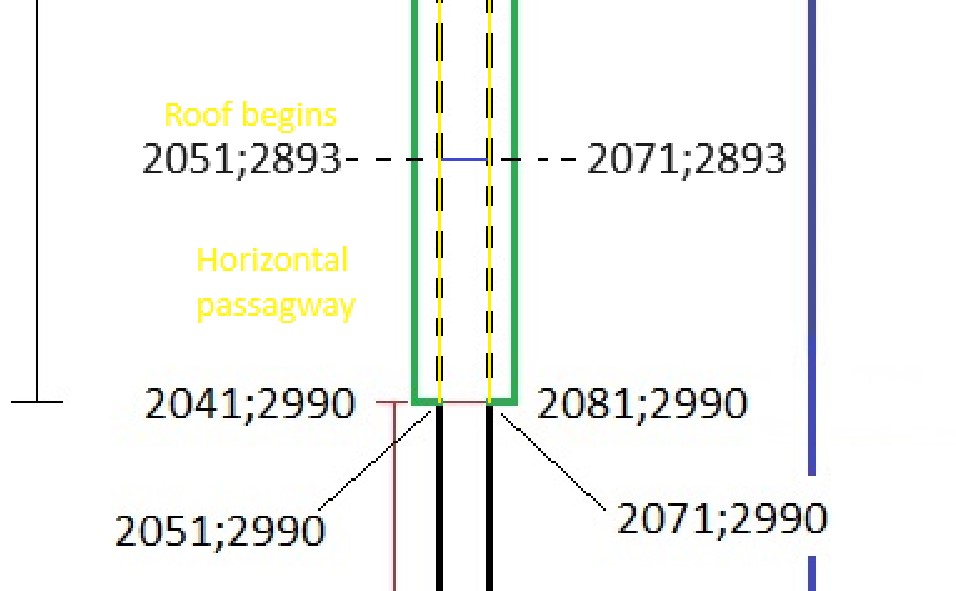
At the step in the floor, at the distance 63,39 cubits RM from the door (or northern wall), the roof level is 43,70 cubits RM equal to 437 pixels. the total height of the pyramid is 280 cubits NM equal to 2800 pixels. The coordinate for the level of the floor at that point is 2800 - 437 =2363, which is 0,2 cubits (or 2 pixels) less the roof level where the roof begins. The height of the passageway at the step in the floor, just before the step
is increased to (2365 - 2363) / 10 = 3,2 cubits, which seems to be unchanged to door opening at the Queen´s chamber.


