Grand Gallery
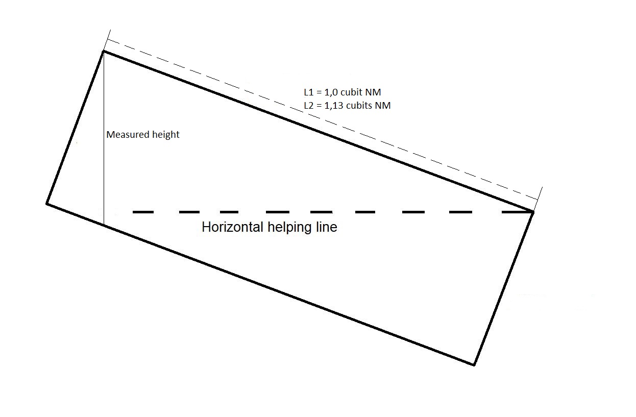
Section 5.5.1
The 10th of January 1988 when I and my wife came out from the ascending passageway and could straighten ourselves up, we saw the amazing Grand Gallery.
A breathtaking view I will never forget.
For this experience I owe King Khufu, his genius architects, his administrative and logistic staff and also all his specialized workers many thanks for this fantastic result. The Grand Gallery looked like the path to heaven - (maybe this was exactly the intention).
Section 5.5.2
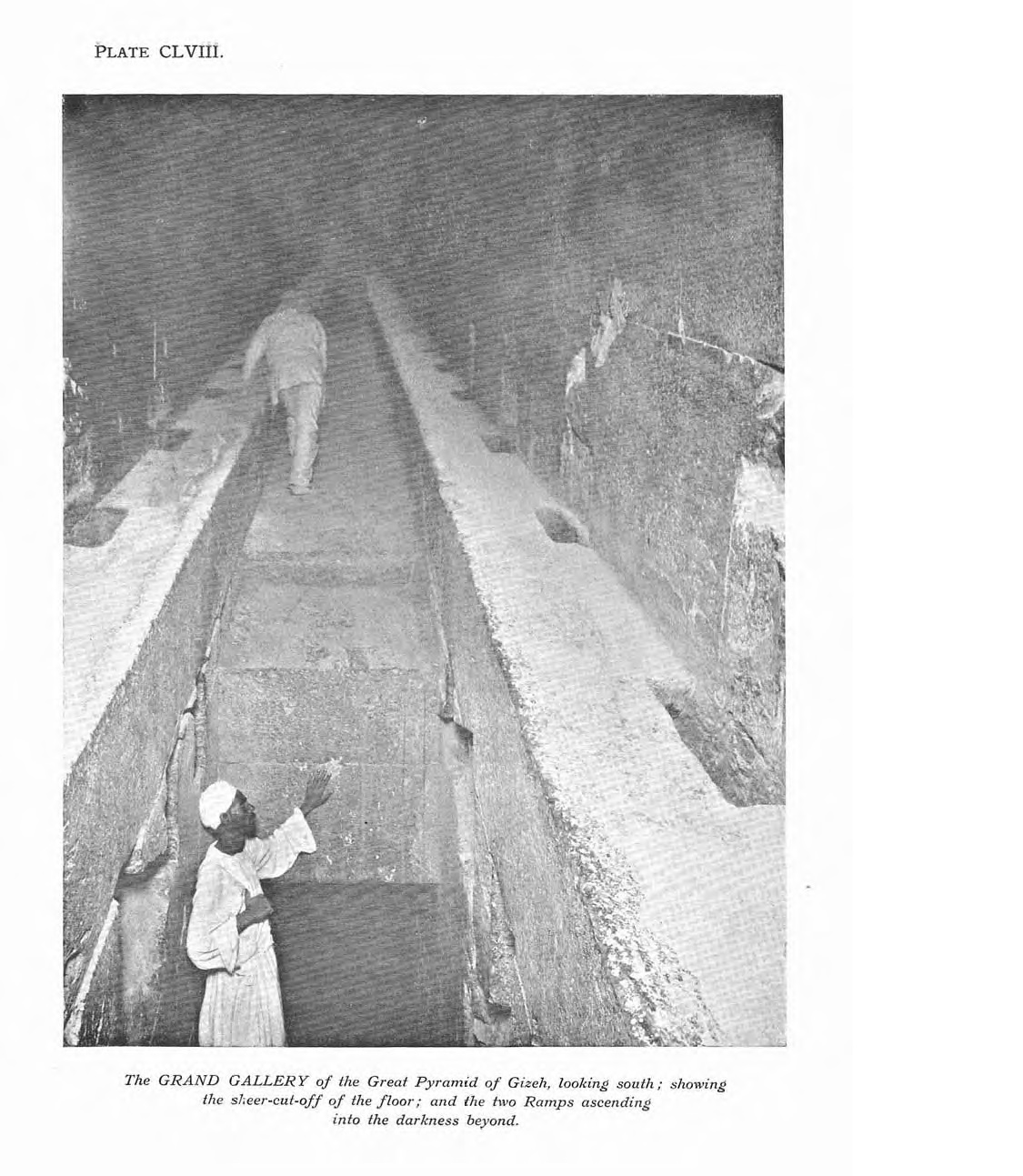
Here is a picture taken by Edgar in 1910 from the floor, the lowest part, of the Grand Gallery, looking South. Behind the helper you can see the passageway into the "Queens chamber".
You can hardly see the end of the Grand Gallery, it is ascending into the darkness like the sky in the night.
Source: The Great Pyramid Passages And Chambers" Volume 1 by John and Morton Edgar, 1910
Section 5.5.3
Flinders Petrie had these valuable comments to the angle and position of the Grand Gallery floor:"For the angle of the passage, and its straightness, it will be well to consider it all in one with the gallery floor, as they were gauged together all in one length."
(S5orig-[S39]-P64-L27-29)
"This , when corrected for lower signal being .3 too high, gives 26° 12´ 50" for mean angle of both passage and gallery together."
(S5orig-[S39]-P65-L2-4)
My comments:
26° 12´ 50" = 26,2139°
"Hence the floor of the gallery intersects the S. wall at 1689.0 +/- .5 above the pavement; at 61.7 +/- .8 S. of the Pyramid centre; "
(S5orig-[S45]-P72-L18-19)
Please observe the lengths informed by Flinders Petrie are always in British inches.
1689 inches = 81,91 cubits. ( = 819 pixels )
61,7 inches = 2,99cubits ( = 30 pixels )
From this we can calculate the coordinate where the floor of the Grand Gallery intersects the Southern wall, which of course is an imaginary point due to the top stone above the ramp.
For a better understanding please see my drawing below, the coordinate we are looking for is in the end of the dotted line:
The coordinate is: (4400/2-30,
2800-819
) = 2170;1981
Now we have the direction and the point where the imaginary floor line meets the South wall of the Grand Gallery.
For 3D designers the line on the floor level from POI 3663;2717 to the point where the imaginary floor line meets the South wall of the Grand Gallery 2170;1981 is:
Y= 0,49297X + 911,26122Please observe that rounding of the numbers in the coordinates creates here and there very small deviations. If you for example calculate the angle of the ascending passageway inclusive the Grand Gallery based on the above mentioned coordinates you will get 26,2418°. Compared to the accepted angle of 26,2139° there is a deviation of 0,0279°.
Section 5.5.4
Let us start where we came into the Grand Gallery from the ascending passageway. The old picture below is showing the end of the ascending passageway where it continues a bit into the Grand Gallery. On the right side you can see the lowest part of the eastern ramp-bench.
Source: The Great Pyramid Passages And Chambers" Volume 1 by John and Morton Edgar, 1910
It seems there had been a mechanical abrasion in the middle part of the floor of the end of the ascending passageway. Please observe the picture was taken before 1910, which is before the massive entry of tourists as we see nowadays. There is a similar abrasion in the top stone in the high end of the Grand Gallery. Please see section 5.5.9
I assume the abrasions were caused during the building of the pyramid.
Section 5.5.5
If we turn around, then the left (eastern) side and the right (western) side at the floor of the Grand Gallery differs from each other. The workers removed a couple of stones on the western side of the ramp-bench near the northern wall to make a passage downwards to the descending passageway. The mouth of this passageway is shown here by some drawings and a photo by Mr. Edgar.Source: The Great Pyramid Passages And Chambers" Volume 1 by John and Morton Edgar, 1910
Underneath is a drawing which shows the well from another angle.
Source: The Great Pyramid Passages And Chambers" Volume 1 by John and Morton Edgar, 1910
The old photo underneath shows the same. There is still a part of the original stone in the western corner of the Grand Gallery.
Source: The Great Pyramid Passages And Chambers" Volume 1 by John and Morton Edgar, 1910
Interesting comment from Piazzi Smyth:
"Further, the hole spoken of as in the floor of Grand Gallery, is rather to one side of it, being within the limits of the western ramp, which has been broken away at the place, for the purpose. In fact there is every appearance that the entrance to the well was once completely closed, by the continuance of the ramp along the western side, similarly to what is now seen along: the eastern. Under such circumstances, strangers would have passed through the Grand Gallery without suspecting any neighbouring well, or concealed passage of any kind ; and it seems probable that it must have been opened by men ascending the well from its entrance below and bursting open its closed ramp-stone ; when, thanks to the extraordinary strength of the cement employed in all the joints, a portion of the said stone was left sticking in the north-west corner of the Gallery, where it may still be seen, testifying to the once completion of the ramp."
Source: (S20-P81-L5-23)
My comments and theory:
There are two interesting aspects here:
1. Originally the "Well"
was sealed, so it was not possible to see it, if (or when) intruders should
arrive in the Grand Gallery for the first time. They just saw the floor, the
walls and the two ramp-benches and the roof. This fact creates a mystery: When
all the passageways and chambers were finished and cleaned up by the workers,
how did they escape from the Grand Gallery? They could have escaped through the
ascending passageway, and somehow released the block stones, which glide down
the ascending passageway. But, if they should pass the three block stones, then
these should have been placed in the Grand Gallery on a bridge of wooden planks
between the doorway to the ascending passageway and the floor between the
ramp-benches. The problem is, there were no reports of wooden planks in the
Grand Gallery. If the Muslim intruders saw the remaining of the wooden planks,
would they have removed them? I doubt, they were looking for gold.
The workers could have escaped through the "Well" before they sealed
the hole. Imagine the last worker should drag the 3-500 kgs stone to the right
place and somehow place it very tight between the other stones in the
ramp-bench. Even if it was possible to drag it, how should he prevent the stone
falling into the "Well"? If there were a supporting stone in the
"Well", then how did he drag it? Unbelievable.
Luckily there is a third possibility: When everything was made, the western
ramp-bench was sealed, so nobody could see it and the three block stones were
sent down the ascending passageway, then they entered the Antechamber to the
"Kings" chamber, sealed the Antechamber and were hewn up together
with all the wooden planks by ropes before the last stone was laid in the roof
of the Grand Gallery. It is certainly a possibility, but that means the
king Khufu was not buried in the known part of the pyramid. If it was true,
then the pyramid of Khufu had only a religious purpose. Would the Egyptians
have built a huge masonry for a religious purpose only? Why not? Huge buildings
for gods are everywhere, for example huge temples, cathedrals, churches.
2. Piazzi Smyth mentioned the block(s) were removed from the passageway underneath;
I am not so sure. If you see the above picture, then you can clearly see scratches
here and there from different tools. It is more likely the ramp-bench have been
opened by force from the Grand Gallery. Some of the intruders found the way up
and could have signaled by knocking where stone(s) should be removed.
Still, the purpose of the "Well" and the passageway from the Grand
Gallery to the descending passageway remains unknown.
Section 5.5.6
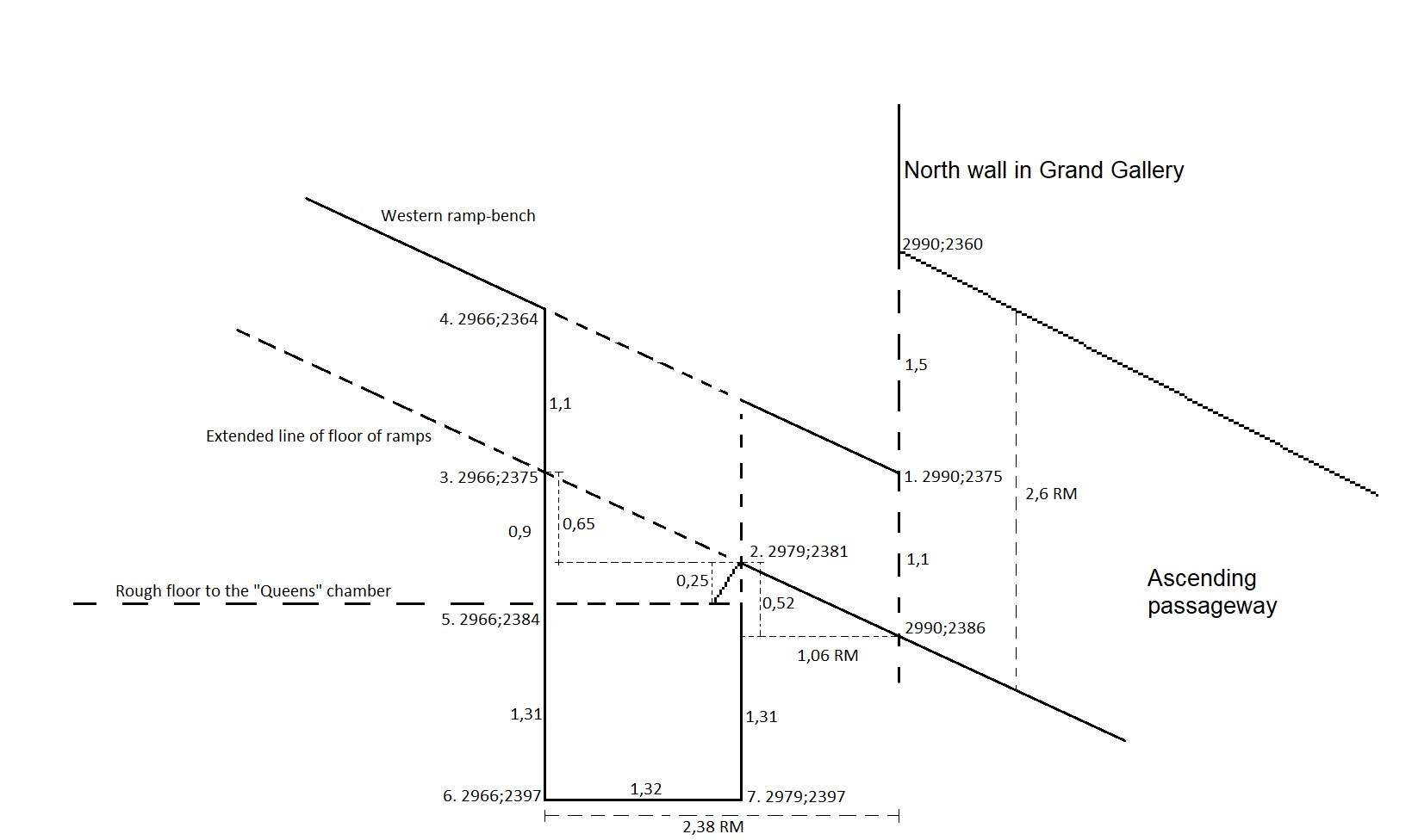
Let us have a closer look on the well showing the western wall and ramp-bench in the Grand Gallery to the left and the end of the ascending passageway to the right:
(I have made a full line to show the supposed original intention of the corner where the upper part of the ramp-bench hit the Northern wall. Above picture in the previous section 5.5.5, you can see the corner is broken.)
Flinders Petrie measured the position of the well from the Northern wall:
"As, however, the position of its mouth has been supposed to have a meaning, it should be stated that the opening is from 21,8 to 49,0 horizontally from N. wall of gallery on floor."
(S5orig-[S46]-P74-L26-28)
My comments:
21,8" = 1,06 cubits RM
49,0" = 2,38 cubits RM
Flinders Petrie measured also the offset on the eastern ramp to the floor from the North wall to the the position of the well from the North wall to the ramp end in the South:
"20,9"
(S5orig-[S45]-P71-L24)
My comments:
20,9" = 1,0 cubit RM
Please observe that the offsets on the western and eastern ramp-benches varies from 20,7" (1,00 cubit) to 21,5" (1,04 cubits) and from 20,3" (0,98 cubits) to 21,6" (1,05 cubits), respectively.
On this point of the western ramp-bench the vertical height is :
1 / cos 26,2139° = 1,1 cubits
The mouth of the well in North South direction is then 2,38 cubits RM - 1,06 cubits RM = 1,32 cubits.
Please see additional calculations in section 5.5.7 regarding the floor level of the Queens chamber.
The height from the floor of the Queens chamber is 2384 - 2375 = 9 pixels = 0,9 cubits.
0,9 cubits - 0,52 cubits = 0,25 cubits
Concerning the depths of the Well, please see figure of Edgar in the section 5.5.7
With measures in cubits:
And coordinates:
Section 5.5.7
Calculations for the coordinates:1. (2990; 2386 -11) = 2990;2375
2. 1,06 * tan 26,2139° = 0,52 cubits and (2990 - 11; 2386 - 5) = 2979;2381
3. 1,32 * tan 26,2139° = 0,65 cubits and (2979 - 13; 2381 - 6) = 2966;2375
4. (2966; 2375 - 11) = 2966;2364
5. (2966; 2800 - 416) = 2966;2384
6. (2966; 2384 + 13) = 2966;2397
7. (2966 + 13) = 2379; 2397
Special remarks:
Flinders Petrie has a measure from ground zero to the floor level 52" = 2,52 cubits from the door opening which is 858,4" = 41,6295 cubits, which corresponds to 416pixels.
In the calculation no. 5 I refer to this. My ground zero has the value 2800 minus 416 = 2384
The point of the mentioned measure is (2990 - 25; 2384) = 2965;2384, which is close to the MASTER coordinates 2966;2384 and an acceptabel error.
Source: (S5orig-[S40]-P66-L4)
In calculation no. 6 is added as the hole depth is 27" = 1,31 cubits RM according to Smyth:
Source : (S20-P71-L39)
Section 5.5.8
The drawings in section 5.5.6 are "close view" versions with another solution. Therefore the calculations and coordinates differs from the overview drawing.
The solution is 446 pixels per 2.6 cubits, which is 171.5 pixels per cubit.
1. 1043-182; 739-86 = 861;653
2. 861-226; 653-103 = 635;550
3. 635; 550-189 = 635;361
4. 635; 366+189+154 = 635;704
5. 635; 704+225 = 635;929
6. 635+226; 929 = 861;929
1,1 cubits = 189 pixels is the vertical height between ramp floor and ramp-bench.
0,9 cubits = 154 pixels is the vertical height between the floor to the "Queens chamber" and the ramp floor extended line.
0,6 cubits = 103 pixels is the vertical height between the ceiling of the passageway to the "Queens chamber" and the ramp floor.
1,31 cubits = 225 pixels is the vertical height between the floor of the well and the floor of the passageway to the "Queens chamber" .
0,33 cubits = 51 pixels is the vertical height of the step at the end of the ascending passageway.
1,3 cubits = 223 pixels is the vertical height between the floor of the well and the end of the ascending passageway .
1,32 cubits = 226 pixels is the horizontal length in the bottom of the well.
0,5 cubits = 86 pixels is the vertical height between the floor of the G.G. and the end point of the floor of the ascending passageway in G.G.
1,06 cubits = 182 pixels is the horizontal length from the well to the Northern wall in G.G.
1,5 cubits = 257 pixels is the vertical height between the ramp floor extended line and the end point of the ceiling of the ascending passageway.
1,1 cubits = 189 pixels is the vertical height between the floor of the ascending passageway and the ramp floor extended line at the Northern wall in G.G.
2,6 cubits = 739-293 = 446 pixels is the vertical height in the ascending passageway.
1043,293 is end point ceiling of ascending passageway
1043,550 is end point ramp-bench into the North wall of G.G.
1043,739 is end point floor of ascending passageway
Section 5.5.9
Let us take a detailed look into the Southern part of the Grand Gallery. As mentioned in section 5.5.3 we have the direction and the point where the imaginary floor line meets the South of the Grand Gallery which is (2170,1981).First an overall view:
The complete length of the Grand Gallery:
And closer to the top stone:
Flinders Petrie:
"At the upper end of the gallery, we have already stated the S. wall to be 61,7 +/- ,8 S. of the Pyramid centre; and hence the face of the great step at the head of the gallery (which descends behind both floor and ramps) is (61,7 - 61,3) = ,4 +/- ,8 S. of the Pyramid centre."
Source: (S5orig-[S46]-P74-L33-36)
My comments:
The mentioned measures above are as usual i inches.
61,7" = 2,99 cubits RM
61,3" = 2,97 cubits
0,4" = 0,02 cubits
My drawings is limited to an accuracy of 1 decimal in cubits, so the width is rounded up to 3 cubits RM.
The 0,02 cubits cannot not be shown in my drawing as the measure is below the 1 pixel, but in this case I have chosen to show it on the drawing even 1 pixel is equal to 0,1 cubits, which is 5 times bigger than the real value. This decision does not have an impact on the position of the South wall.
Flinders Petrie:
"And the sloping floor seems to be also out of level by an equal amount in the opposite direction; since on the half width of the step (i.e. between the ramps) the height of the step face is 34,92 or 35,0 on E., and 35,80 or 35,85 on W."
Source: (S5orig-[S46]-P75-L9-11)
My comments:
On East side:
34,92" = 1,69 cubits RM
35,0" = 1,70 cubits RM
On West side:
35,80" = 1,74 cubits RM
35,85" = 1,74 cubits RM
It is clear the top stone or "step" is not perfectly horizontally. In my drawings it does not really matter as the accuracy is limited to +/- 0,1 cubits. The result is therefore the same on both sides : 1,7 cubits RM (which is 17 pixels).
We know from section 5.5.6 that the vertical height of the ramp-bench is 1,1 cubits.
The vertical height from the ramp-bench to the edge of the top stone is therefore 1,7 cubits - 1,1 cubits = 0,6 cubits.
Flinders Petrie:
"Then the top of the step will (by above measures) be here 34,88 above actual floor end, and the step dips about ,64 to the S.wall at this part; so the top of the step at the S. wall is 34,88 + ,64 -30,08 = 4,16 (say+/-,2) above the virtual floor end at the line of taping."
Source: (S5orig-[S46]-P75-L18-21)
My comments:
34,88" = 1,69 cubits RM
0,64" = 0,03 cubits RM
30,08" = 1,46 cubits RM
4,16" = 0,2 cubits
With measures all in cubits:
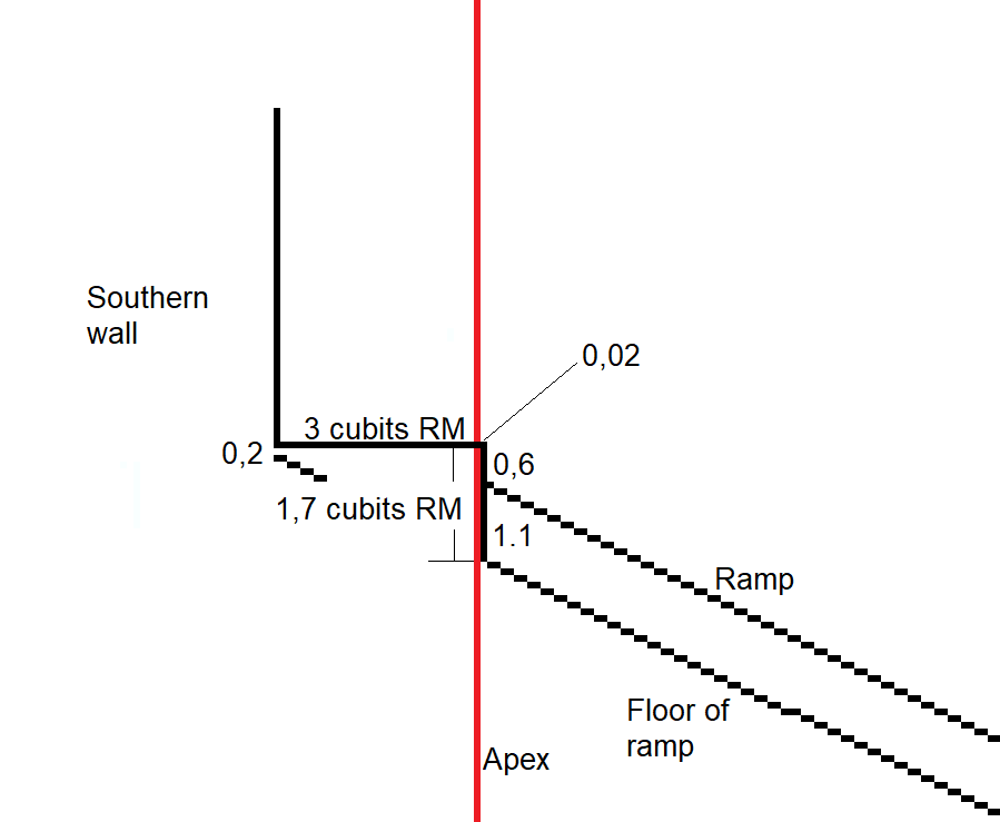
It is impressive how close the Northern edge of the top stone is on the Apex - the middle of the pyramid. The distance is 0,02 cubits RM is equal to 1 cm !
I assume it was the intention to place the edge of the top stone in the middle of the pyramid. The idea might have been to mark a point between the ascending structure and the entrance of the passageway to the antechamber and the "Kings" chamber, which hereafter is horizontal.
With coordinates:

From section 5.5.3 we calculated the coordinate where the floor of the Grand Gallery intersects the Southern wall is (2170,1981).
The top stone intersects with the southern wall at (2170,1981-2) = (2170,1979).
The North-South length of the top stone is 3 cubits. the northern edge is therefore (2170 + 30,1979) = (2200,1979) which is shown in the drawing as ("2201",1979) to mark the small difference from Apex.
The height from the edge of the top stone to the ramp-bench is 0,6 cubits, the ramp intersects to the top stone at ("2201",1979 + 6) = ("2201",1985).
The vertical height of the ramp is 1,1 cubits, the floor of the ramp intersects to the top stone at ("2201",1985 + 11) = ("2201",1996).
A much closer look on the intersection between the imaginary line and the upper face of the top stone is here:
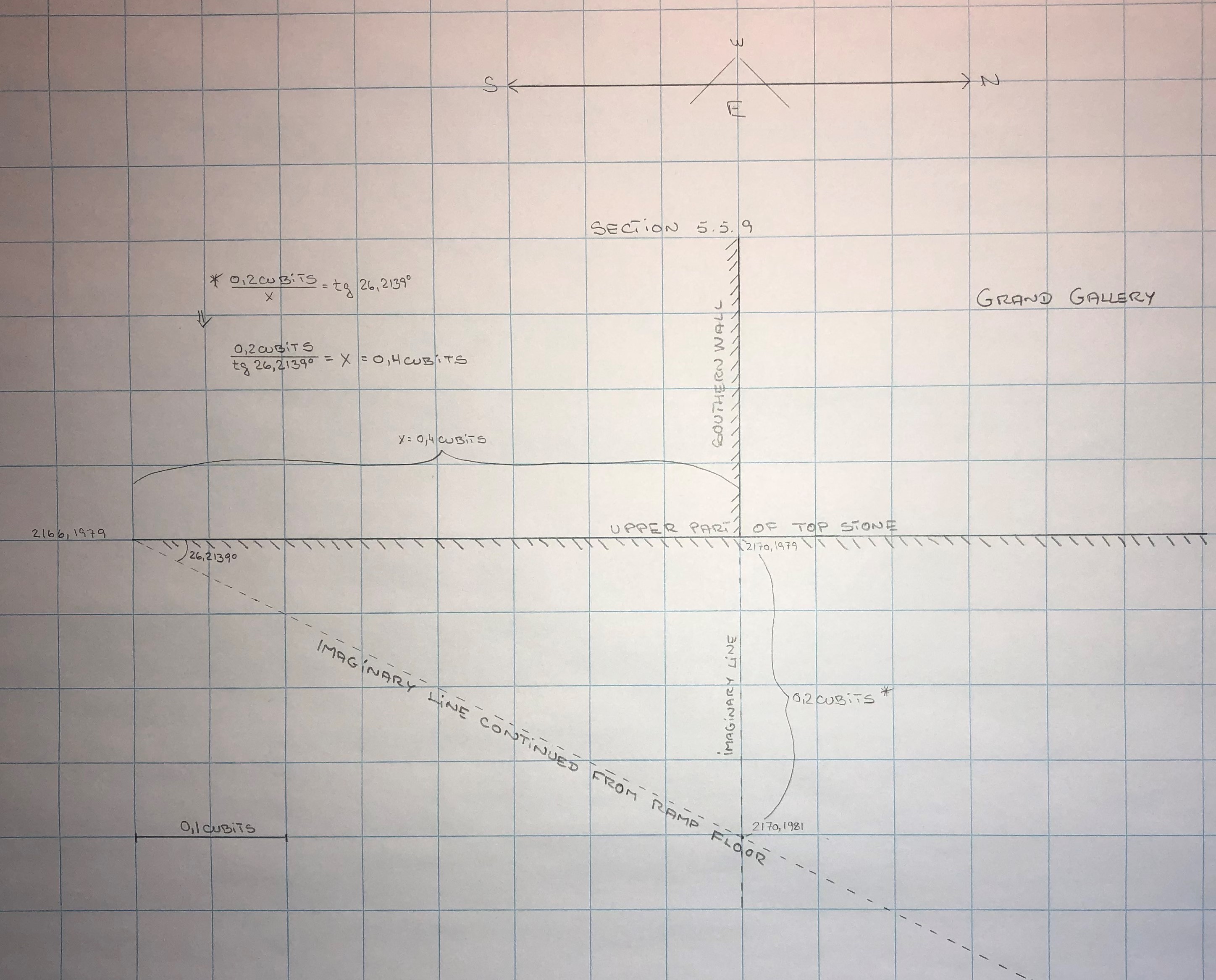
As you can see the imaginary line , which is prolonged from the floor of the ramp, hit the floor of the Antechamber only 0,4 cubits (=21 cm) from the edge of the Southern wall in the Grand Gallery.
Charles Rigano mentioned "The single block forming the Step does not stop at the Gallery wall but extends an additional 66" into the Ante Chamber".
Source: (S11-P53-L15-16)
My notes:
66" = 3,2 cubits
Flinders Petrie mentioned in a table:
Source: (S5orig-P75-table)
My notes:
61,32" = 3 cubits RM (Face of the Northern edge of the step to the Southern wall of Grand Gallery)
64,90" = 3,14 cubits RM (Length from the Southern wall to the joint where the granite begins)
As Flinders Petrie measured along the floor and the top stone is a lime stone then the length of the top stone in the North - South direction is 3 cubits + 3,14 cubits = 6,14 cubits RM in total.
I think it is an interesting structure as the Southern wall secure the top stone and prevents the stone from moving - especially downwards into the depths of the Grand Gallery. The top stone could withstand a huge downwards force during the construction of the pyramid.
Are there any indications of forces which had been applied to the top stone?
Edgar took a photo of the top stone, which gives you a better idea how it looks like. It was taken against the South - West corner of the Grand Gallery:
Source: The Great Pyramid Passages And Chambers" Volume 1 by John and Morton Edgar, 1910
Nowadays the top stone has been "repaired", maybe to avoid any accidents when tourists move around on the stone.
It is more or less the same kind of a mechanical abrasion in the middle part of the top stone as we saw in the floor of the Grand Gallery, see in section 5.5.4 . In 1910 it could still be seen. If you examine the picture carefully you can see a trace in the middle of the eroded part of the top stone. It looks like a rope has been running there. If this is so, then the top stone somehow has been a part of the building process of the pyramid.
Lowest in the picture you can see the ascending floor of the Grand Gallery and on both sides there are ramp-benches leading up the top stone. On the Western side a piece of the ramp-bench has been broken off.
In the background you can see the entrance to the small passageway to the antechamber and hereafter the "Kings" chamber.
Section 5.5.10
Let us have a closer look on the old picture.
Source: The Great Pyramid Passages And Chambers" Volume 1 by John and Morton Edgar, 1910
1. It is not possible to judge whether the missing part of the top stone is due to an abrasion or made for a purpose. If you ignore the angle from which the photo is taken, then it seems the top stone has a smooth surface in the rounded part from the vertical center of both the ramp-benches . There is a possibility the shape has been made by the workers for a purpose.
2. If you examine the line under "2", then it starts from the very top of the top stone and ends at the bottom of the rounded part.
3. Where the line "2" ends you see a clear round abrasion, which could have been made by a running rope. Under the rounded abrasion is a vertical abrasion, which could have been caused by a rough rope or by water to cool down the rope caused by the friction against the stone.
4. Just above the "4" point there is a line that could have been caused by a stone which the workers dragged up and hit the top stone hard because of an accident.
If any of my readers have another explanation, please let me know.
I have tried to make a drawing by hand from the North side: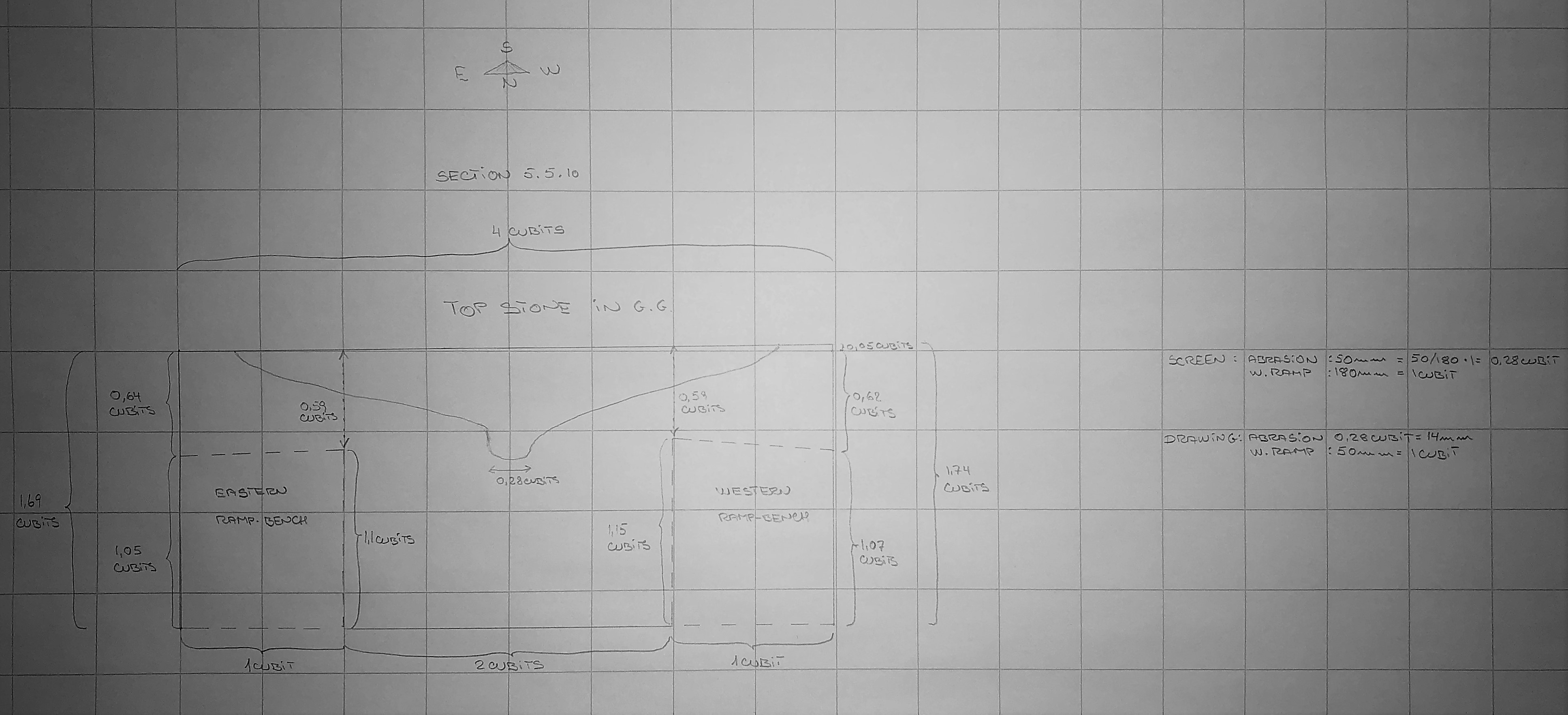
It is hard to figure out how far the abrasion hit the top stone in the North - South direction, but a photo taken nowadays give us a good indication: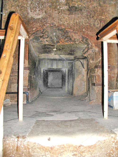
Source:
https://commons.wikimedia.org/wiki/File:Herses-grande-pyramide.jpg
The line which forms a half circle behind the banister is the border between the original top stone and the repaired part. The repaired part seems to begin on the middle of the top stone.
The top stone seen from above:
I must introduce a new source S20 :
Life And Work at The Great Pyramid, during the months of January, February, March and April, A.D. 1865 by C. Piazzi Smyth, Vol. II, Edinburgh, Edmonston And Douglas 1867.
The problem with this source is the way Piazzi Smyth measured. As I have learned the measurements were not as accurate as Petries. On the other hand we have no other choice as Petrie did not measure everything and from time to time he referred to Piazzi Smyths work.
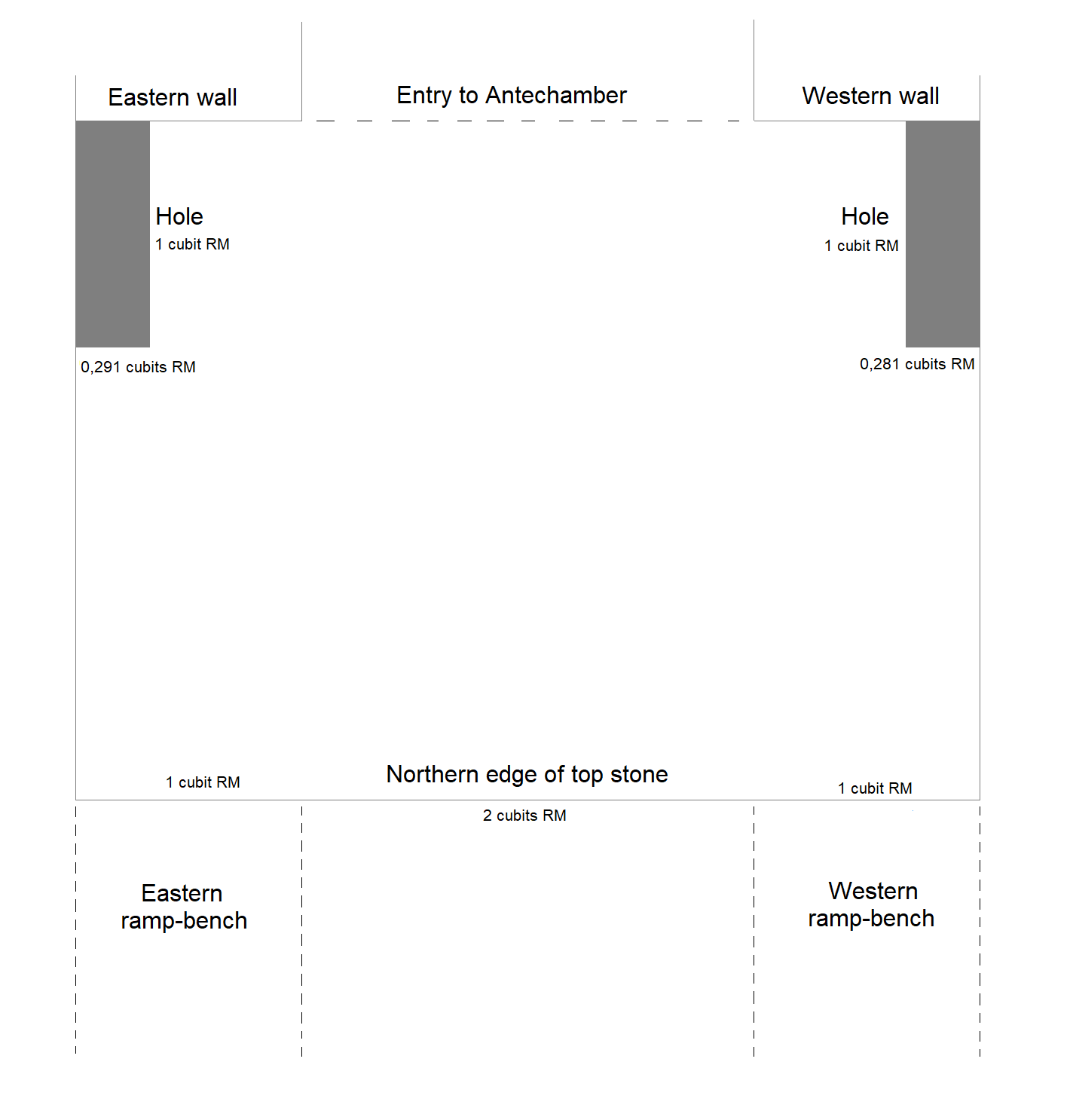
Smyth measured the depths of the holes in the Grand Gallery - also the depths of the two holes in the top stone:
(Table: "Ramp-holes on East side. On step, 28")
"Breadth from East to West 6,0"
"Depth, vertical 5,5 "
Source: (S20-P80-Last line in the table)
My comments:
6,0" = 0,291 cubits
5,5" = 0,267 cubits
(Table: "Ramp-holes on West side. On step, 28")
"Breadth from East to West 5,8"
"Depth, vertical 5,? "
Source: (S20-P81-Last line in the table)
My comments:
5,8" = 0,281 cubits
5,0" = 0,242 ??? cubits (It seems this measure is uncertain).
The width of the ramp-benches and the width between the ramp-benches are measured by Smyth:
"Grand Gallery, Breadth over ramps, . . . = 82,0" " between ramps, . . . = 42,0"
Source: (S20-P71-L1-L2)
My comments :
82,0" = 3,98 cubits RM (in drawings this result is rounded up to 4,0 cubits).
42,0" = 2,04 cubits RM (in drawings this result is rounded down to 2,0 cubits).
With measures:
The East-West coordinates are:
2041;2200-30 = 2041 (E-W) ;2170 (N-S)
2041;2170+10 = 2041 (E-W) ;2180 (N-S)
2041+3;2180 = 2044 (E-W) ;2180 (N-S)
2044;2180-10 = 2044 (E-W) ;2170 (N-S)
Western hole:
2081;2200-30 = 2081 (E-W) ;2170 (N-S)
2081;2170+10 = 2081 (E-W) ;2180 (N-S)
2081-3;2180 = 2078 (E-W) ;2180 (N-S)
2078;2180-10 = 2078 (E-W) ;2170 (N-S)
I have tried to make a 3D drawing of the top stone seen from North to South. I apologize for the low quality of my work - I am not used to make these drawings :
You can read the measures and the coordinates are mentioned below in a table.
Section 5.5.11
Let us focus on the top surfaces of the ramp-benches. On the picture in section 5.5.2 you can see rectangular holes cut down in the ramp-benches close to the walls. You can also see niches behind the holes cut into the walls.Please see the drawing below of Mark Lehner showing an example of a hole (3) (here called notch) in the ramp (1), the niche (4) and the trapezoidal cutting (5) in the wall (2) parallel to the ramp:
Source S15,
"Niches, Slots, Grooves and Stains: Internal Framework in the Khufu Pyramid?" of Mark Lehner published in
https://www.academia.edu/36645718/Niches_Slots_Grooves_and_Stains_Internal_Frameworks_in_the_Khufu_Pyramid
Section 5.5.11
Unfortunately Flinders Petrie did not register the number of holes, but he had following remarks:"One remarkable point is that the holes are alternately long and short, on both sides of the gallery; the mean of the long holes is 23´32, with an average variation of ´73, and the mean of the short holes is 20´51, with average variation of ´40. Thus the horizontal length of a long hole is equal to the sloping length of a short hole, both being one cubit. This relation is true within less than half their average variations."
Source: (S5orig-[S46]-P72-L27-32)
My remarks:
Long hole: 23´32 inches = 1,13 cubits RM; ´73 inches = 0,04 cubits
Short hole: 20´51 inches = 1,0 cubit RM; ´40 inches = 0,02 cubits
Another important measure Flinders Petrie mentioned:
"Ramp End ... 1815´5 Distance on Slope"
Source: (S5orig-[S45]-P71-L39)
My remarks:
1815,5" = 88,0456 cubits RM, which in my drawings I round down to 88 cubits.
Charles Rigano wrote following remarks:
"At the top of each platform 25 niches are cut into each wall (total 50) most of which have an angled trapezoidal feature chiseled across its face. There are 27 rectangular holes cut downwards into each side platform (total 54). The rectangular holes are next to the walls and generally centered on the niches cut into the side walls; the two rectangular holes against the north (lower) face of the Gallery do not have companion side niches.
All of the 50 side niches and trapezoidal features are completely filled with blocks and mortar of the type used elsewhere in the pyramid with the exception of the 7th and 11th side niches from the bottom on the west side, the first of which is empty and the second has a hole cut into the mortar. Because the depth of only two side niches is known, we cannot determine if opposing side niches were of different depths to facilitate insertion of a beam as is the case with the holes at the entrance to the Upper Horizontal Passage".
Source: (S11-P51-L16-26)
On the same page he wrote in a table :
"Depth (Into Platform) 7,0" - 11.5"
Width (From Gallery Wall) 5,5" - 6,5"
Source: (S11-P51-L10 in the table)
On page 50 Charles Rigano mentioned following measures in the table:
"Width - Bottom Including Side Platforms 6´ 10" (4 cubits)
Width - Between Side Platforms 3´ 5" (2 cubits)
Side Platforms 20,5" Wide 20,5" High (1 cubit square)"
Source: (S11-P50-L7 in the table)
My remarks:
7" = 0,34 cubits RM and 11,5" = 0,56 cubits RM. (depths)
5,5" = 0,27 cubits RM and 6,5" = 0,32 cubits RM. (widths)
Luca Miatello inform following in source 15:
"The holes are 14 cm wide, 18 cm deep, and their mean length alternates regularly between 52,1 cm (one cubit) and 59,2 cm (Petrie, 1883:72)."
My remarks:
There are 27 holes on each ramp-bench.
If you see the picture in section 5.5.9 it is obvious there is no hole adjacent to the top stone.
As these measurements are incomplete I must refer to the work of Piazzi Smyth again as a plan B. The reason I am a bit worried using the data from Piazzi Smyth, is following remark from Petrie:
"By successive rod measures, Prof. Smyth made the gallery 0,8 shorter than it appears by this continous measure ; but the continuous measure is certainly better in principle and also in practice, as we have seen in the other passages."
Source: (S5orig-[S45]-P7-L7-9)
My comments:
0,8" = 0,04 cubits
Anyway, the deviation in this case seems to be very small. Piazzi Smyth measured all the holes and the spaces between them.
Here is an overview of the measurements on the eastern ramp-bench:
Source:
(S20-P80-The table)
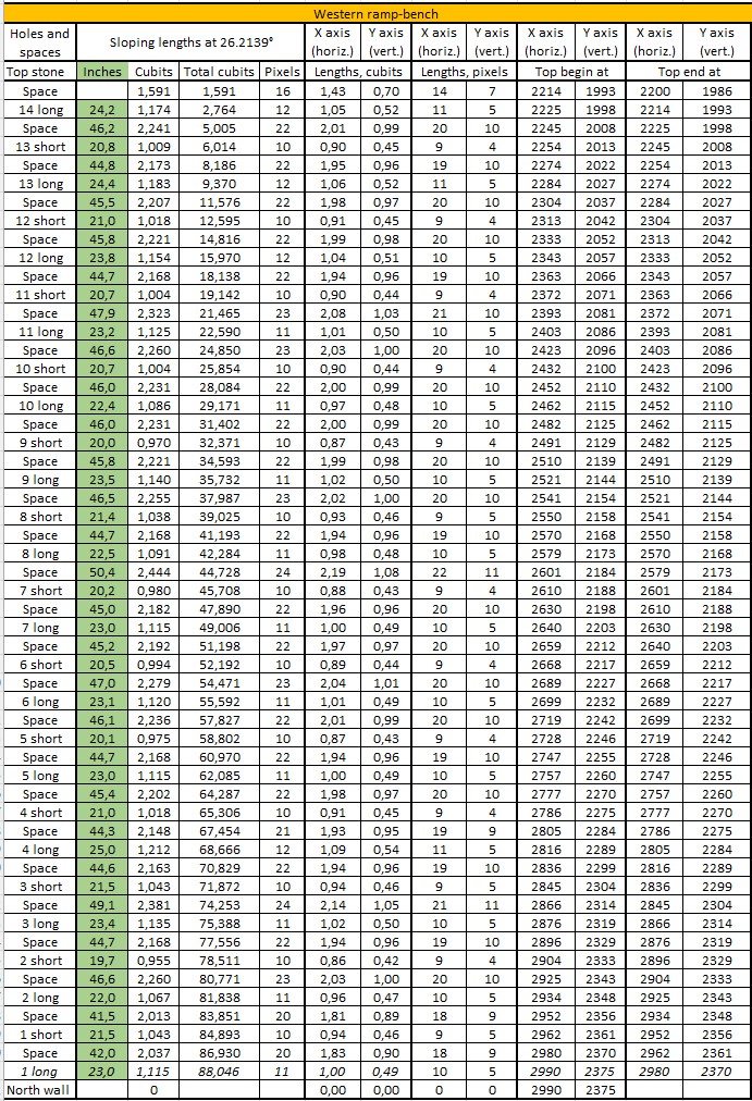
Here is an overview of the measurements on the western ramp-bench:
Source: (S20-P81-The table)
I have converted the tables into cubits. The green marked cells are the above measurements. Please observe the value in "Space" between the "14 long" hole and the "Top stone" is calculated as the difference between 88,0456 cubits and the total of the measurements.
Here are the sloping lengths for the holes and the spaces between the holes:
Calculation methods:
Cubits = Inches x 20,62Example: 1,140 = 23,5 x 20,62
Total cubits:
Example: 2,779 = 1,140 + 1,639
Pixels:
Example: 11 = 1,140 x 10 (rounded to zero decimals)
Calculation methods:
Cubits = Inches x 20,62Example: 1,174 = 24,2 x 20,62
Total cubits:
Example: 2,764 = 1,174 + 1,591
Pixels:
Example: 12 = 1,174 x 10 (rounded to zero decimals)
The "1 long" hole on the western ramp-bench is broken.
The coordinates for the holes in the eastern ramp-bench are:
Calculation methods:
X axis (horiz.), lengths, cubits:Example: 1,02 cubits = 1,140 x COS 26,2139° (rounded to 2 decimals)
X axis (horiz.), lengths, pixels:
Example: 10 pixels = 1,140 x COS 26,2139° x 10 (rounded to zero decimals)
X axis (vert.), lengths, cubits:
Example: 0,50 cubits = 1,140 x SIN 26,2139° (rounded to 2 decimals)
X axis (vert.), lengths, pixels:
Example: 5 pixels = 1,140 x SIN 26,2139° x 10 (rounded to zero decimals)
Please see further details underneath in section 5.5.12
The coordinates for the holes in the western ramp-bench are:
Calculations follow underneath in section 5.5.12
The vertical depths of the holes in the eastern ramp-bench are:
The yellow marked fields were not measured, so I have calculated and inserted a mean value.
The total is 5,747 cubits divided by 14 = 0,41 cubits.
The vertical depths of the holes in the western ramp-bench are:
The yellow marked fields were not measured, so I have calculated and inserted a mean value.
The total is 11,164 cubits divided by 25 = 0,45 cubits.
Section 5.5.12
The holes look like this:The bottom of the holes have the same slope as the ramp-benches (26,2139°) and the sides of the holes are perpendicular to the bottoms.
The holes may have been made before the stones were mounted in the Grand Gallery.
The sloping lengths of the holes alternate between approximately 1,13 cubits and 1,0 cubit starting at the North wall with a long.
From the table above Piazzi Smyth measured the vertical length inside the hole.
To find the coordinates on the upper corners C1 and C2 of the holes we need some help lines:
The sloping length is SL.
X = SL x COS 26,2139°
Y = SL x SIN 26,2139°
The northern hole ("1 long") in the eastern ramp-bench start with a coordinate at the northern upper corner (C2) at 2990;2375
X = 1,115 cubits x COS 26,2139° = 1,00 cubits equal to 10 pixels
Y = 1,115 cubit x SIN 26,2139° = 0,49 cubits equal to 5 pixels.
As my coordinatsystem starts at 0;0 in the upper left corner of the screen then C1 is:
(2990-10 ; 2375-5) = 2980;2370
Part of the above table:
The next step is the lower corners C3 and C4, here we need more help lines:
As you can see there are two triangles.
The first consists of the sides "a", "b1" and "c", the second consists of "a", "d" and "e".
c = d x COS 26,2139°
In the second triangle we know:
a = c x SIN 26,2139°
b1 = c x COS 26,2139°
We can insert c in the calculations of the second triangle:
a = d x (COS 26,2139°) x (SIN 26,2139°)
b1 = d x (COS 26,2139°) x (COS 26,2139°)
The coodinates of C4 and C3 can then be calculated.
Example, (the same hole as above) :
a = 1,115 cubits x (COS 26,2139°) x (SIN 26,2139°) = 0,21 cubits equal to 2 pixels.
b1 = 1,115 cubits x (COS 26,2139°) x (COS 26,2139°) = 0,43 cubits equal to 4 pixels.
Coordinate for the corner C4 :
(2990 -2 ; 2375 + 4) = 2988;2379
Coordinate for the corner C3 :
(2980 -2 ; 2370 + 4) = 2978;2374
Part of the above table:
Section 5.5.13
Please see my detail drawings of the holes of the Grand Gallery. It shows the holes in the eastern ramp-bench, the western ramp-bench is similar except the escape passageway near the northern entrance.
S = Short hole
L = Long hole
The eastern ramp-bench:
The western ramp-bench:
For internal use only:
The above drawings are as pixel lengths x 2 = cubits x 20 = New lengths.
Local drawing coordinates:
0,0 : Top, left
Initial coordinates:
Surface of ramp-bench as it hit the northern wall : 1675;1900
Surface of ramp-bench as it hit the top stone : 95;1122
Angle of surface of ramp-bench : 26,2139°
- (1675; 1900 - 1,5 cubits x 20 ) = 1675;1820
- (1675; 1900 + 1,1 cubits x 20 ) = 1675;1922
- (95; 1122 + 1,1 cubits x 20 ) = 95;1144
- (95; 1122 -0,6 cubits x 20 ) = 95;1110
- (95 - 3 cubits x 20 ; 1110 ) = 35;1110
- (35; 1110 + 0,3 cubits x 20 ) = 35;1116
- (35 + 1,0 cubit x 20; 1116 ) = 55;1116
- 55;1110
- (1675 - 1,06 cubits x 20 ; 1922 - 0,52 cubits x 20 ) = 1654;1912
- (1654; 1912 0,25 cubits x 20 ) = 1654,1917
- (1654; 1912 - 1,1 cubits x 20 ) = 1654;1890
- (1654; 1917 + 1,3 cubit x 20 ) = 1654;1943
- (1654 - 1,32 cubits x 20; 1937 ) = 1628;1943
- (1628; 1937 - 1,0 cubit x 20 ) = 1628;1917
- (1628; 1917 - 0,9 cubits x 20 ) = 1628;1899
- (1628; 1899 - 1,1 cubits x 20 ) = 1628;1877
For internal use only :
For internal use only :
Overview of the holes in the detail drawing, for internal use only:
Section 5.5.14
The width of the holes is measured partly by Piazzi Smyth; where he miss to measure I have also here calculated a mean value and marked these yellow.
In the eastern ramp-bench the variation is from 0,291 cubits RM to 0,330 cubits RM.
In the western ramp-bench the variation is from 0,267 cubits RM to 0,315 cubits RM.
In all cases the pixel value is 3.
The East-West coordinates are as follows:
Section 5.5.15
The eastern ramp-bench:
The western ramp-bench:
Section 5.5.16
The first holes according to the above overview:
Section 5.5.17
In section 5.5.13 you saw this excellent drawing of Mark Lehner:Source S15, "Niches, Slots, Grooves and Stains: Internal Framework in the Khufu Pyramid?" of Mark Lehner published in https://www.academia.edu/36645718/Niches_Slots_Grooves_and_Stains_Internal_Frameworks_in_the_Khufu_Pyramid
Compare the drawing to this photo:
Source: S17. http://grahamhancock.com/phorum/read.php?1,269522,269576
(Hole 4L)
and to another photo:
http://thepyramids.org/p-016-great-pyramid-khufu-cheops-233-039-cavity-grand-gallery.html
For those who has not visited the pyramid I can assure you both photos and the drawing are correct. Let me explain:
Mark Lehner call the rectangular holes for "slots" and above the "slots" are "niches" cut into the wall. Across the niches are chiseled a trapezoidal structure called "trapezoidal cutting". In my opinion it is not a trapezoidal structure, but a parallelogram as both the opposite sides are parallel.
Anyway, in "Niches, Slots, Grooves and Stains: Internal Framework in the Khufu Pyramid?" by Mark Lehner published in https://www.academia.edu/36645718/Niches_Slots_Grooves_and_Stains_Internal_Frameworks_in_the_Khufu_Pyramid :
"4. The niches, numbering 25 were cut, 18 to 20 cm deep and 67 cm high, into the side walls above all but the upper southermost and lower nothermost of the notches. The top and bottom edges are horizontal. the bottom north corners are even with the sloping top of the ramp benches while the south corner is 10 - 13 cm lower, consequently part way inside the accompanying notch. The outer top and north edge of at least some of the niches are bevelled.
5. The niches were closed with limestone patch (Flicken) or plugs. The beveled edges were filled with mortar. The bottoms of the patch stones slope even with the slope of the upper surface of the bench-ramp. Below this, the niches were filled with limestone fragments and mortar. L. BORCHARDT reported that, where the patches had broken or the mortar fill had fallen away, the well-trimmed inside surfaces of the niches were fresh, clean and white as though they were little used before being closed by the patches.
6. Trapezoidal cuttings, (Streifen, striures, incisions) about 2 to 3 cm deep, were chiseled across the patched niches and onto the adjacent wall surface. The cuttings are 10 cm above the tops of the ramp benches and roughly parallel to the slope of the ramp-benches. The lengths of the cuttings vary from 55 to 70 cm. The cuttings are missing from the northernmost patched niches at the low end of the Grand Gallery."
Source: (S15-P102-L17-32)
According to Charles Rigano there are 25 holes out of 27 in each ramp-bench which have these niche and trapezoidal features. Charles Rigano wrote following in the book "Pyramids of the Giza Plateau":
"All of the 50 side niches and trapezoidal features are completely filled with blocks and mortar of the type used elsewhere in the pyramid with the exception of the 7th and 11th side niches from the bottom on the west side, the first of which is empty and the second has a hole cut into the mortar."
Source: (S11-P51-L21-23)
In the figure on the same page mention Charles Rigano some figures in a table:
"Side Niches (In Walls") :
Height: 26"
Width: 11"
Depth: 8"
Source: (S11-P51-table)
My comments: The first picture is hole marked 4L ( or the 7th hole ) showing the empty hole and the 11th hole is the hole marked "6L".
Section 5.5.18
With other words, the only niche we can describe is the one connected to hole marked 4s, which is a short one. All the other niches might be of the same sizes, but we cannot be sure. The consequence of this is, that I avoid to calculate the coordinates for all other niches.As you can see on the picture, it has not been easy to measure the dimensions of the niche at the short hole 4L and different sources have different answers:
The hole 4L has following dimensions:
Length: 1 cubit RM
Width: 0,27 cubits RM
Depth: 0,34 cubits RM
The angle is: 26,2139°
The niche has following dimensions from sources in a certain order, where Mark Lehner is the most reliable :
Depth:
Mark Lehner: 18-20cm , Source: ( S15-P102-L17), equal to 0,34-0,38 cubits
Miatello: 20cm , Source: ( S16-P3-1C-L7) , equal to 0,38 cubits
Rigano: 8" , Source: (S11-P51-table) , equal to 0,388 cubits
The depth of the niche at 4s is 0,38 cubits.
Height:
Mark Lehner: 67cm , Source: ( S15-P102-L17) , equal to 1,28 cubits
Miatello (source S16): 60cm (average) , Source: ( S16-P3-1C-L26) , equal to 1,146 cubits
Rigano: 26" , Source: (S11-P51-table) , equal to 1,261 cubits
The height of the niche at 4s is 1,28 cubits.
Width:
Mark Lehner: ?
Miatello: 32 cm , Source: ( S16-P3-1C-L26) , equal to 0,61 cubits
Rigano: 11" , Source: (S11-P51-table) , equal to 0,533 cubits
See below.
Southern bottom corner in the hole:
Mark Lehner: 10-13cm , Source: ( S15-P102-L20) , equal to 0,19-0,25 cubits
See below.
It is not the big secret the dimensions "Width" and "Southern bottom corner in the hole" puzzles me. Let me prove what is right and wrong.
Underneath is a drawing of the upper part of hole 4s which is aligned with the surface of the ramp-bench seen from the western side.
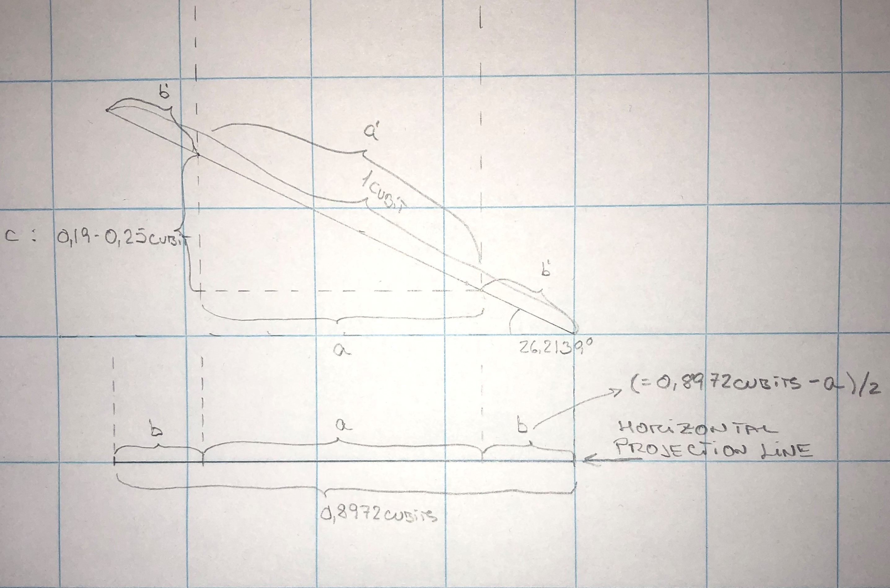
The upper part of the hole 4s is illustrated by a 26,2139° sloping imaginary line with a sloping length of 1 cubit.
The dotted lines in the upper part of the drawing symbolizes the niche.
The northern lower corner of the niche hit the imaginary sloping line of the hole.
The southern lower corner of the niche descend 0,19 cubits to 0,25 cubits into the hole marked "c".
The sloping length of the hole where the niche cut the imaginary line is marked a´
The remaining parts of the sloping line are marked b´ so b´ + a´ + b´ = 1 cubit.
According to Miatello the width of the niche is 0,61 cubits
Rigano has informed the width of the niche is 0,533 cubits
Let us make some calculations to judge who is right, we can make two calculations based on both c = 0,19 cubits and c = 0,25 cubits:
It is obvious that Miatello is not right, it is not possible the width is 0,61 cubits.
Let us turn around and make the calculation of the length c based on the number of Rigano:
which is close to 0,25 cubits mentioned by Mark Lehner.
Rigano has informed the right figure of 0,533 cubits, if the lower southern corner descent 0,25 cubits into the hole 4s.
Does it make sense ? Let us calculate the sloping lengths a´and b´ :
Result:
a´= 0,6 cubits
b´= 0,2 cubits
The so called trapezoidal cuttings has these measures:
(The sides are parallel to the ramp-bench).
Depth:
Mark Lehner: 2-3cm, Source: ( S15-P102-L28), equal to 0,04-0,06 cubits
Miatello: 2-3cm , Source: ( S16-P3-1C-L23) , equal to 0,04-0,06 cubits
The depth of the trapezoidal cuttings at 4s is 0,04-0,06 cubits.
Height:
Mark Lehner: ?
Miatello (source S16): 20cm, Source: ( S16-P3-1C-L24) , equal to 0,38 cubits
The height of the trapezoidal cuttings at 4s is 0,38 cubits.
Length:
Mark Lehner: 55-70cm, Source: ( S15-P102-L17), equal to 1,05-1,34 cubits
Miatello: 55-70cm, Source: ( S16-P3-1C-L24) , equal to 1,05-1,34 cubits
The length of the trapezoidal cuttings at 4s is 1,05 cubits
Lower side above ramp-bench:
Mark Lehner: 10-13cm , Source: ( S15-P102-L29) , equal to 0,19-0,25 cubits
Section 5.5.19
The measures are approximate values, so in this case I have chosen not to add RM. As the figures are not precise it could be helpful to receive a second opinion from the readers.All these figures helped me to issue a drawing, the measures are in cubits:
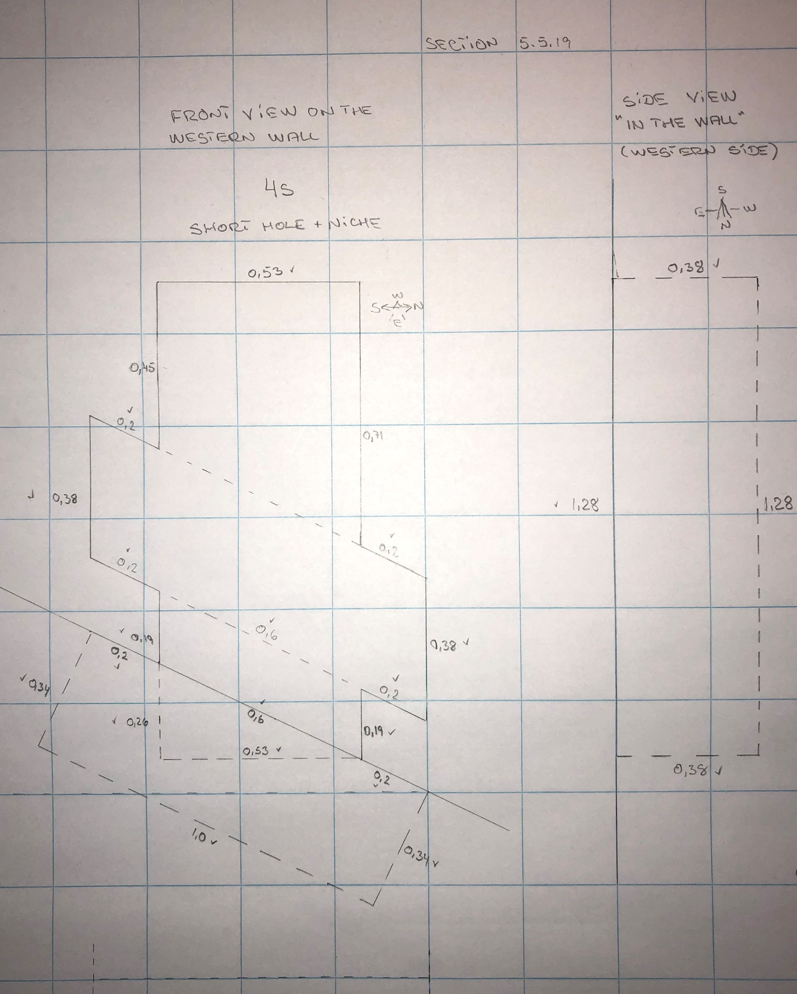
The drawings show the same niche at the hole 4L but seen from two different angles.
As mentioned the measures are not precise. From that perspective I dare to point out that some of measures might have been intended to be the same.
The depth of the hole of 0,34 cubits could have been intended to the same measure as the height of the trapezoidal structure of 0,38 cubits and the depth of the niche of 0,38 cubits as well. Normally I would not play with figures, but in this case I cannot resist. If the intended measure was the average between 0,34 cubits and 0,38 cubits = 0,36 cubits then this value is equal to 0,5 remens or 10 fingers. Is it a coincidence? Maybe - maybe not.
Another interesting measure is the offset of the bottom of the trapezoidal structure above the ramp-bench of 0,19 cubits, which is very similar to the sloping distance of 0,2 cubits, which is the same as 1/5 cubits.
Furthermore the height of the niche is 1,28 cubits which is exactly the same as 9 hands.
We can conclude the measures of smaller structures were defined as a simple fraction of cubits or in natural numbers of remens, hands (palms) or fingers.
Section 5.5.20
Let us see a top view at the floors in the pyramid:We zoom in:
The black lines are the ascending and descending passageways.
The green lines represent the Grand Gallery.
A closer look on the Southern part of the Grand Gallery close to the Apex (center of the pyramid):
And the northern part where the ascending passageway hits the Grand Gallery.
The passageways are East of the North-South center line.
The entrance from the Grand Gallery into the antechamber (southern part of the topstone) at the North-South coordinate 2170 is more or less in the same position as the entrance of the subterranean chamber at 2181, but of course placed higher up in the pyramid. The difference is 9 pixels or 0,9 cubits = 0,471 metres.
Section 5.5.21
Let us focus on the walls and the roof in the Grand Gallery. For this purpose, we need an additional figure in the set of coordinates as the walls and the roof. Until now the coordinates consisted of two coordinates, either (N-S, Up-Down) or (E-W, N-S). Until now it has been sufficient, and we saved some space in the drawings.In this section we need to define an expanded set of coordinates as (N-S, Up-Down, E-W) or (X, Y, Z) as in a "normal" coordinate system.
The four corners where the walls hit the "floors" are:
The northern wall at the eastern corner hits the ramp-bench at: 2990, 2375, 2041
The northern wall at the western corner hits the ramp-bench at: 2990, 2375, 2081
The northern wall at the eastern corner hits the imaginary floor line at: 2990, 2386, 2051
The northern wall at the western corner hits the imaginary floor line at: 2990, 2386, 2071
The southern wall at the eastern corner hits the top stone at: 2170, 1979, 2041
The southern wall at the western corner hits the top stone at: 2170, 1979, 2081
Section 5.5.22
Edgar published a picture of the North side of the Grand Gallery, where you easily can see the corbelled walls on all sides.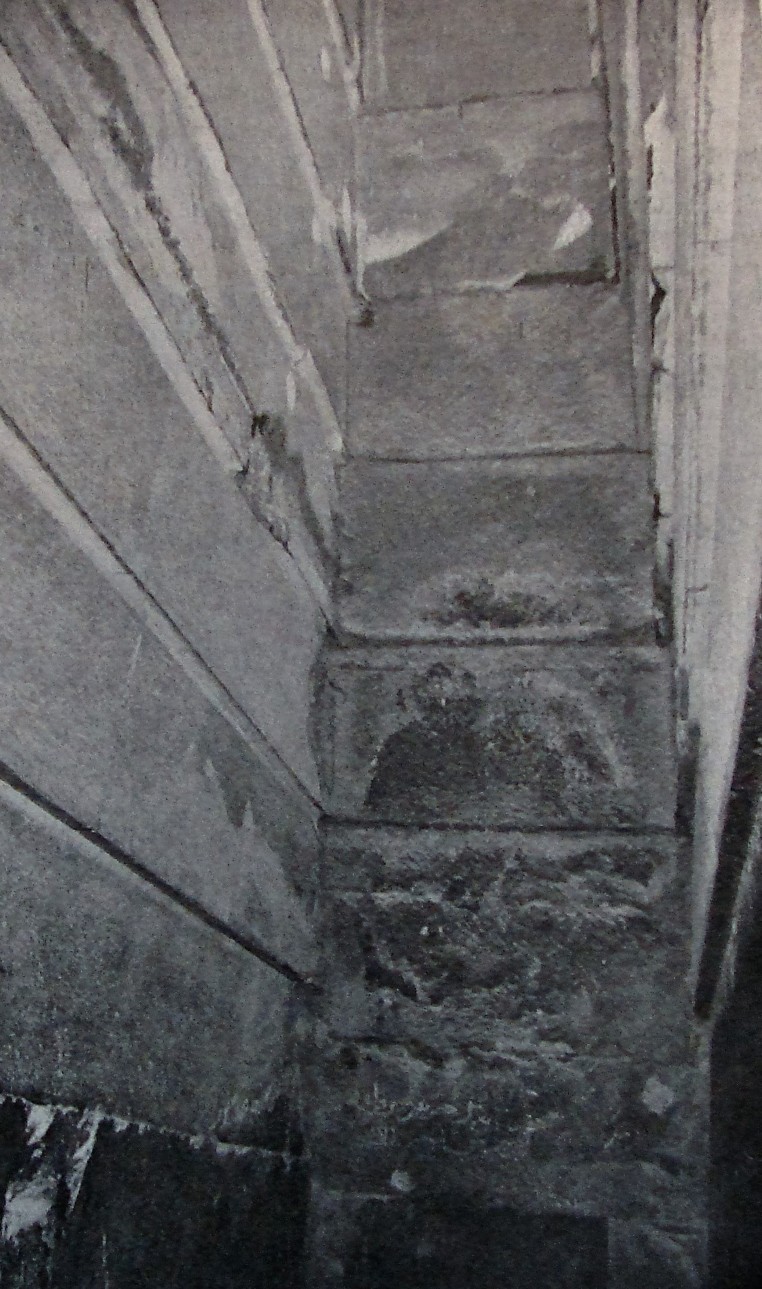
Source: The Great Pyramid Passages And Chambers" Volume 1 by John and Morton Edgar, 1910
A recently taken picture of the walls:
Source: http://www.touregypt.net/featurestories/greatpyramid3.htm
Please ignore the staircase and the angle irons inserted in the walls to prevent fractions falling down. I have chosen this "new" picture to give you a better idea how the walls look like. Even the roof was not made smooth, but the stones are angled. Flinders Petrie had a good explanation:
"The roof of the gallery and its walls are not well known, owing to the difficulty of reaching them. By means of ladders, that I made jointing together, I was able to thoroughly examine both ends and parts of the sides of the gallery. The roof stones are set each at a steeper slope than the passage, in order that the lower edge of each stone should hitch like a paul into a ratchetcut in the top of the walls; hence no stone can press on the one below it, so as to cause a cumulative pressure all down the roof ; and each stone is separately upheld by the side walls across which it lies."
(S5orig-[S46]-P72-L33-40)
Section 5.5.23
All the walls consist of a basis and 7 laps and in the 3rd lap there is a groove on the eastern and western walls, let us see which measures we have:Flinders Petrie:
"The remarkable groove in the lower part of the third lap, along the whole length of the sides, was measured thus, perpendicularly :
(S5orig-[S46]-P73-L40-41)
(S5orig-[S46]-P73-L42-45)
My comments:
N.W. 11,7" = 0,567 cubits RM close to 4 hands RM (palms)
N. E. 11,8" = 0,572 cubits RM = 4 hands RM (palms)
S. W. 11,2" = 0,543 cubits RM
S. E. 11,0" = 0,533 cubits RM
Mean 11,4" = 0,553 cubits RM
N.W. 5,4" = 0,262 cubits RM
N.E. 5,7" = 0,276 cubits RM
S.W. 5,1" = 0,247 cubits RM close to 1/2 foot or 7 fingers
S.E. 5,1" = 0,247 cubits RM close to 1/2 foot or 7 fingers
Mean 5,3" = 0,257 cubits RM
Mean difference -6,1" = 0,296 cubits RM or close to 2 hands (palms)
Flinders Petrie:
"At the S.W. it is cut to a depth of -8 inch, at the S.E. to -6 (?) ; the upper edge of it is often ill-defined and sloping."
(S5orig-[S46]-P73-L46-47)
My comments:
S.W 0,8" = 0,039 cubits RM close to 1 finger.
S.E 0,6" (?) = 0,029 cubits RM (?)
Section 5.5.24
The dimensions in the Grand Gallery is a challenge as my sources miss a lot of genuine measurements. Even my favorite source Flinders Petrie had difficulties to measure for example the vertical height of the Grand Gallery. I have different measures from different sources, and they might be correct all of them depending on where they measured. To understand the problem, I have copied the old drawing of Edgar. I have inserted 4 red lines to visualize the problem. The heights of each lap are missing, also the height of the basis of the walls under the laps.Source: The Great Pyramid Passages And Chambers" Volume 1 by John and Morton Edgar, 1910 (Red lines and blue numbers are added by me).
(You can also see the groove in the third lap mentioned in the previous section).
Line I: Even it has been extremely dangerous to measure this height, it should be possible.
Line II: I cannot imagine this measure has ever been made. But, this height is the "true" vertical height.
Line III: It could be possible to measure there, but it is not the "real" height".
Line IV: This measuring line is very possible and the most convenient, but is it the "true" vertical height?
Section 5.5.25
Another tricky point is that the roof is not smooth, but the stones are angled as explained in section 5.5.22If you see the yellow marked area of the roof of the drawing med by Edgar, then you might understand the measuring problem of the "true" vertical height:
Source: The Great Pyramid Passages And Chambers" Volume 1 by John and Morton Edgar, 1910 (page 64)
Let us examine the different sources:
Section 5.5.26
Luca Miatello made following figure 3:Source: S16. "Examining The Grand Gallery in The Pyramid of Khufu And its Features" by Luca Miatello in PalArch´s Journal of Achaeology of Egypt/Egyptology, 7(6) (2010)
My comments:
I'm not sure where Luca Miatello's measurement results come from, with all due respect I doubt he has measured them himself. Let us for a moment accept the results and compare them with other sources.
Luca Miatello:
"Projections of the seven corbels together: seven palms (one palm each);"
Source: (S16-P6-L22-23)
"Perpendicular height from the gallery floor to the top of the gallery: about 15 cubits;"
Source: (S16-P6-L32-33)
"Note 11: according to Maragioglio & Rinaldi (1965: pl. 6, fig. 1), the vertical height of the gallery varies from 8.48 to 8.74 m, mean 8.61 m, hence: x2 + x2/tan(63.8°)2 = 8.612; x = 7.73 m = 14.8 cubits."
Source: (S16-[C1]-P24-L50-53)
My comments:
The calculation of Maragioglio & Rinald is very doubtful and it is not obviously clear from where the different factors are coming from. As I can calculate X=2,633 m in the above equation, which makes no sense.
8,48 m = 16,196 cubits = 23,904 remens
8,74 m = 16,692 cubits = 23,606 remens
8,61 m = 16,444 cubits = 23,255 remens
7,73m = 14,763 cubits = 20,878 remens
"Perpendicular height from the top of the ramp benches to the top of the gallery: about 14 cubits;"
Source: (S16-P6-L34-36)
"Note 12: the perpendicular height of the ramp benches is 0.52 m, or one cubit; the perpendicular height from the top of the benches to the first corbel is about 1.65 m, or 3.1 cubits: see Maragioglio & Rinaldi (1965: pl. 6, fig. 1)."
Source: (S16-[C1]-P24-L54-56 and S16-[C2]-P24-L1)
"Perpendicular height of the seven corbels together: about 11 cubits."
Source: (S16-P6-L37-38)
My comments:
It is important to observe the measures are calculated and the little innocent word "about" is added in the text, but not in figure 3.
Please observe where the vertical measuring line is placed at the roof, is it placed there by a coincidence?
Source: S16. "Examining The Grand Gallery in The Pyramid of Khufu And its Features" by Luca Miatello in PalArch´s Journal of Achaeology of Egypt/Egyptology, 7(6) (2010)
(This is the upper part of fig. 3 - Yellow markings and blue circles are made by me.)
My comments:
8,6 m = 16,425 cubits = 23,228 remens
Section 5.5.27
Flinders Petrie had following comments:"The depth of two of these ratchetcuts, at the S. end, I measured as 1,0 and 1,9 to 2,0) ; and the angles of the two slabs there 28° 0' to 28° 18', and 27° 56' to 28° 30',
mean 28° 11' ; which on a mean slab 52,2 from N. to S., would differ 1,74 inches from the passage slope. The edge of the southernmost slab is 14,5 from the S. wall ; the next slab is 47,4 from N. to S."
Source: (S5orig-[S46]-P72-L40-41) followed by (S5orig-[S46]-P73-L1-4)
My comments:
28° 0' to 28° 18' = 28,0° to 28,3° = 13,16 seked to 13,00 seked
27° 56' to 28° 30' = 27,9° to 28,5° = 13,22 seked to 12,89 seked
mean 28° 11' = 28,18° = 13,07 seked
52,2" = 2,532 cubits RM = 3,580 remens RM
1,74" = 0,084 cubits RM = 0,119 remens RM
14,5" = 0,703 cubits RM = 0,994 remens RM
47,4" = 2,299 cubits RM = 3,251 remens RM
As the measurements of the angle are so different from each other, it makes sense to choose the mean value as Petrie suggested, though the original intention might very well have been 13,0 seked NM equal to 28,3° NM.
See also section 5.5.32
Flinders Petrie:
"According to Prof. Smith the mean height of this lap above the gallery floor is 166,2 ± 0,8 vertically ; hence the groove is at 172,1 to 179,0 vertically over the floor, and its lower edge is therefore at half the height of the gallery, that varying from 167 to 172."
Source: (S5orig-[S46]-P73-L47) followed by (S5orig-[S46]-P74-L1-3)
My comments:
166,2" = 8,06 cubits RM = 11,399 remens RM
0,8" = 0,039 cubits RM = 0,055 remens RM = 1,086 fingers RM
172,1" to 179,0" = 8,346 cubits RM = 11,803 remens RM to 8,681 cubits RM = 12,277 remens RM
167" to 172" = 8,099 cubits RM = 11,454 remens RM to 8,341 cubits RM = 11,797 remens RM
Section 5.5.28
Charles Rigano mentioned:"Incline at Ceiling: 28° 11'
Height - Vertical : 28' 2" "
Source: S11-P50 in the table.
My comments:
28° 11' = 28,1833°
28' 2" = 16,397 cubits = 23,189 remens
Section 5.5.29
Mark Lehner and Zahi Hawass mentioned:"Height 8,7 m (28 ft 6 in.)"
Source: S12-P152-[C1]-L3
My comments:
8,7 m = 16,616 cubits = 23,498 remens
28 ft 6 in = 16,591 cubits = 23,463 remens
Section 5.5.30
Mark Lehner mentioned:"The Grand Gallery is a stupendous achievement: the roof soars to 8,74 m (26 ft) and is the glorious culmination a series of corbelled roofs seen at Meidum and Daschur."
Source: S13-P112-Lines under the picture of Grand Gallery
My comments:
8,74 m = 16,692 cubits = 23,606 remens
26 ft = 15,14 cubits (I assume the 26 ft is a print error, maybe it should have been 28 ft) ?
Section 5.5.31
As you may understand, to measure the height of the Grand Gallery is not easy and to bring the results to the public is even worse because the roof has the ratchetcuts and the roof is angled 28,18°, which is more than the floor of the Grand Gallery. The floor and the floor of the internal ramp is smooth but the roof is not. Let us examine the roof in detail.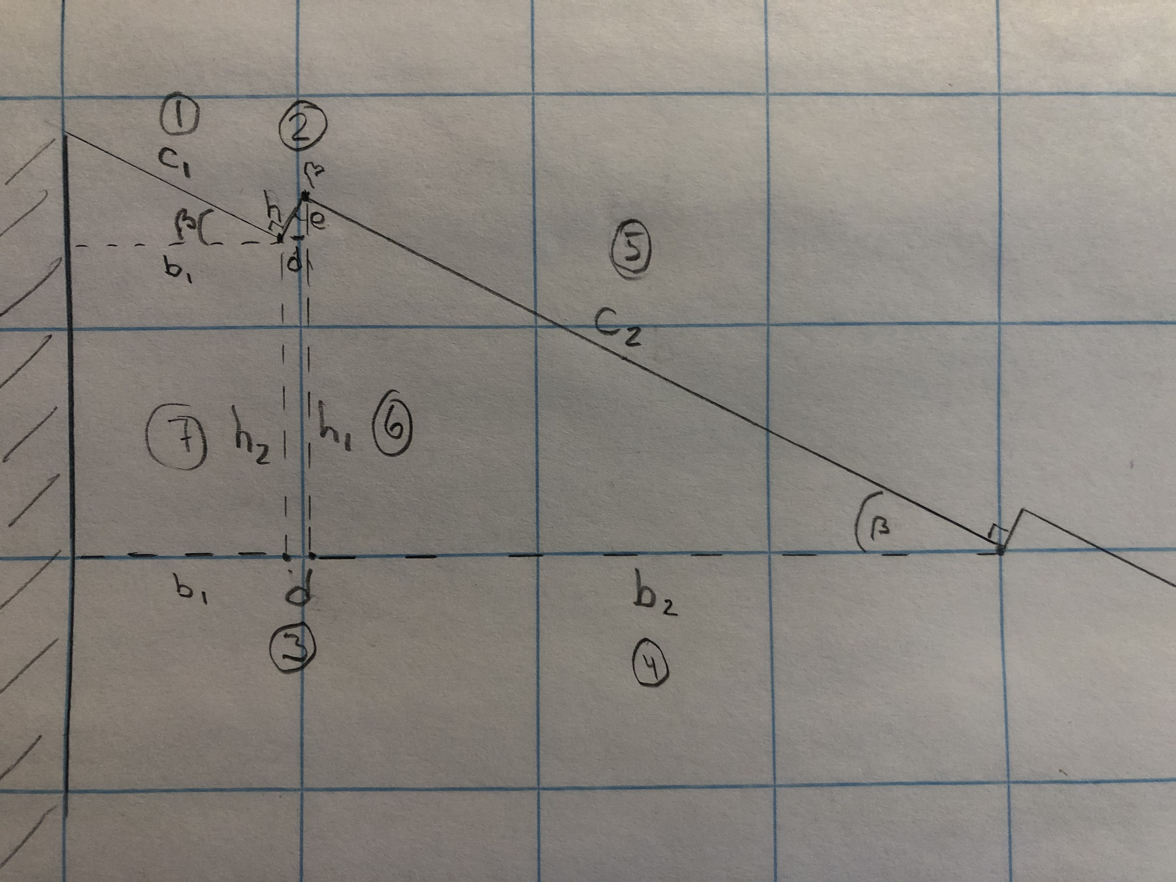
From section 5.5.27 we know following measures:
h : 1" and 1,9" to 2,0" = 0,048 cubits RM and 0,092 cubits RM to 0,097 cubits RM. (Petrie) (Basically two measures, we check which of them is correct).
β : Mean angle 28,18° (Petrie) (There are 4 different measures 28,0° and 28,3° and 27,9° and 28,5°. With this diversity it is fair to accept the mean value).
b2 or c2 : Mean slab 52,2" = 2,532 cubits RM (Petrie) (It is not crystal clear whether Petrie referred to the sloping c2 or horizontal b2, we will check this).
b1 : 14,5" = 0,703 cubits RM (Petrie)
b2 or c2 ?
If we compare the calculations in step 4 and step 5 then the results in step 5 is much more aligned with "Mean slab 52,2" = 2,532 cubits RM (Petrie)" than step 4.
We can hereby conclude that Petrie meant the sloping length c2. The mean sloping length of the slab is 2,532 cubits RM.
Section 5.5.32
Now we know c2 is 2,532 cubits RM, then we can calculate the real value of b2:h1 is:
Let us check the mean angle 28,18° :
2,2319 cubits x 7 hands / 1,1957 cubits = 13,07 seked, which is very close to 13 seked. b2 and h1 is therefore verified.
If the angle should have been exact 13,0 seked, then h1 should have been 1,2018 cubits, a deviation of 0,0061 cubits, which is far under the accuracy in this work as mentioned earlier.
"The depth of two of these ratchetcuts, at the S. end, I measured as 1,0" and 1,9" to 2,0"
Source: (S5orig-[S46]-P72-L40 ) se also section 5.5.27
Section 5.5.33
Back to the height of the Grand Gallery. In the sections 5.5.24 and 5.5.26 we saw different possible measuring lines and it is even more complicated as the slabs in the roof elevate with another angle than the floor of the Grand Gallery. However it looks like the mean elevation of the roof is the same as the elevation of the floor. We can check this easily if we imagine a line from one upwards corner to the next downwards corner.It is the same as in section 5.5.27, but in this I have inserted a triangle where the corners of the hypotenuse hit the downwards corners.
The angle β = 28,18° as mentioned in section 5.5.27 and the angle alpha is the one we check whether it is the same angle as the elevation of the floor 26,2139°.
It is obvious the angle is not the same as the angle of the floor independent of the depth of the ratchet-cut are measured as 1,0" or 1,9" to 2,0" . So, this measure is still unclear, though the angle of the floor as 26,2139° is very close to 26,484°. which derived from the measure of the ratchet-cut as 2,0".
If the elevation of the ceiling was exactly the same as the elevation of the floor, them the depth of the ratchet-cut should have been:1,76" is in between of the set of measures, but 1,76" was not measured and cannot be accepted as a mean value.
Another interesting point concerning the measured and possible depths of the ratchet-cuts is the number of fingers:
1,0" = 1,4 fingers RM
(1,5" = 2,0 fingers)
(1,76" = 2,4 fingers)
1,9" = 2,6 fingers RM)
2,0" = 2,7 fingers RM)
Unless all depths of the ratchet-cuts are measured we cannot verify the exact depths and as the deviation is so small, we leave it as it is - not verified.
Section 5.5.34
Piazzi Smyth measured following heights of the Grand Gallery:
Source:
(S20-P86-The table)
I have tried to clean the results:
I have calculated all measures in cubits RM :
And in remens RM as well :
Section 5.5.35
Based on above measurements, it is possible to calculate the coordinates for the start points and end points of all the measurements.Please observe the measurement in the first line is based on the top of the step of the protruding floor from the ascending passageway.
The measurements in the lines 2 to 6 are based on the horizontal rough floor leading to the "Queens chamber".
The measurements in the lines 7 to 15 are based on the inclined floor between the two ramp-benches.
The first table written in green is for internal use only. The detailed drawing underneath is based on these coordinates.
The real coordinates are in the next table.
The end positions of the measuring lines give an idea about where the roof is.
The next drawing shows a detail view at the northern wall.
Section 5.5.36
I admit Piazzi Smyth did very detailed measurements of the walls and the heights, so I have decided to continue with his data.Underneath is a table with his measurements on the northern wall with the overlaps.
Please observe the lowest overlap is not made in this wall of an unkown reason.
Source: (S20-P89-The table)
I have issued a "cleaned" version:
Parenthesis in an Excel sheet is the same as a negative number, so I have indicated these measures with red ink instead.
Please observe, the total of height 344,0" or 16,7 cubits RM is measured from the top of the step of the protuding passage floor from the ascending passageway.
This height is stated as 344,2" in the table by Piazzi Smyth in section 5.5.34, but the error is very little and has no influence on coordinates or drawings.
The same oveview, but in cubits RM:
Again, but here you can read the coordinates for the overlap corners in the northen wall:
Part of the master drawing:
And a detailed drawing with the lines showing the the measured heights:
Closer view of the northern wall:
The arrow shows where the first overlap "should have been".
Detail drawing with MASTER coordinates:
Section 5.5.37
Underneath is a table with Smyths measurements on the southern wall with the overlaps.Source: (S20-P90-The table).
A "cleaned" version:
Parenthesis in an Excel sheet is the same as a negative number, so I have indicated these measures with red ink instead.
The same table, but in cubits RM:
Calculations of the pixels in the drawing for the overlap corners in he southern wall:
The coordinates for the overlap corners in the southern wall:
The detail drawing of the Grand Gallery with the southern wall as well:
A closer view on the southern wall:
The following coordinates are for internal use only, these are for the detailed drawing with a better solution:
Master coordinates in detail drawing:
Section 5.5.38
Smyth had this comment:
"Examined the roof-stones of Grand Gallery, by a strong light from below, and made their number from north to south = 36."
Source: (S20-P86-L3-5)
As mentioned in section 5.5.33 the roof stones were not mounted regularly, so I have given up to calculate the coordinates for the lower and upper corners for all the roof stones. For those who are eager to try, I can add a valuable information from Petrie as mentioned in section 5.5.27:
"The edge of the southernmost slab i 14,5 from the S. wall; the next slab is 47,4 from N. to S."
Source: (S5orig-[S46]-P73-L2-4)
My comments:
14,5" = 0,703 cubits RM = 0,994 remens RM
47,4" = 2,299 cubits RM = 3,251 remens RM
If I draw a straight line at the roof, (the roof is not at all straight), from the coordinates (2980;2214 to 2180;1818 from the drawing), then we can see the deviations compared to the measurements:
The straight line is Y = 0,495 * X - 738,9
Calculated values of deviations:
Of these 15 measurements we can read the minimum deviation is -0,04 cubits and the maximum deviation is 0,73 cubits. The average deviation is 0,31 cubits.
The tendency line for the measures is Y = 0,4895 * X - 756,5 , with a bit different slope than the straight line mentioned above and the tendency line is also parallel shifted, which is not surprising as the roof stones are angled a bit more than the Grand Gallery.
Section 5.5.39
Petrie mentioned:"From this the length of the roof of the gallery is 1688,9- 40,45 = 1648,4 horizontal, or 1838,6 sloping."
Source: (S5orig-[S46]-P73-L2-4)
My comments:
1838,6" = 89,17cubits
The length of the straight line Y = 0,495 * X - 738,9 from section 5.5.38 from the 2980;2214 to 2180;1818 is 89,26 cubits.
The deviation beween Petries and mine calculations of the sloping length of the roof is 89,26 cubits - 89,17 cubits = 0,09 cubits or 4,7 cm only !
Section 5.5.40
What is above the roof of the Grand Gallery? The roof stones are mounted like this:It is nearly impossible to add stones horizontally on the top of the roof. I assume there is an empty space above the roof. How far upwards this empty space extents is impossible to judge.
By the way:
In November 2017 experts from France, Japan and Egypt published a large study of the pyramid based on muons tomography and infrared thermography, which showed a cavity above the Grand Gallery.
Source:
Scanpyramids - Wikipedia
Section 5.5.41
Let us see how lines of the overlappings look like :Here is the same drawing flipped horizontally:
Please focus on the yellow marking.
Flinders Petries mentioned following:
"At the top of the N. end is a large forced hole, cut by Vyse in 1837, and still quite fresh-looking. The whole of the top lap of stone is so entirely cut away there that I could not decide to where it had come, and only suppose it to project 3 inches, like the others."
Source: (S5orig-[S46]-P74-L9-12)
Source: (S20-P89-90-Plate 10).
I assume the dotted line is the observed edge of the block. It seems the blocks continue angled downwards behind the northern wall.
My construction ramp theory:
Imagine the blocks of the two walls in the Grand Gallery run down to the ground on both sides of the descending passageway, the ascending passageway and the Grand Gallery. Please see the lines again, this is a part of the construction ramp. Maybe the two construction ramps were extended more or less all over the northern side. In this case it was possible to move many stones up at the same time, which reduced the construction time considerably!
The construction ramp had therefore an incline of 26,2139° which is quite steep, so to reduce the friction the workers lubricated the ramps all the time. Another argument for this theory: If the construction ramp was something else then all these stones in the ascending passageway and the Grand Gallery should be moved up to a certain level and afterwards angled when they were mounted - no way.
Another interesting point is the northern parts of the roofs of the "Queens chamber" and the "Kings chamber" were angled in the same way and the huge stones on the top of the "Kings chamber" could have been moved up these ramps and fitted nicely. If you extend the lines of the overlaps in the Grand Gallery, you can see the idea clearly.
Please see the drawing of Edgar below:
Source: The Great Pyramid Passages And Chambers" Volume 1 by John and Morton Edgar, 1910
Section 5.5.42
The overlappings in the East -West direction are as follows at the southern wall:
Source: (S20-P91- table).
At the northern wall:
Source: (S20-P89-lower table).
I have created an overview with estimated coordinates for all the corners:
The marked figures are eye-estimated. Not all coordinates of the corners are accurate.
The N-S figures and calculations derives from section 5.5.37There are too many uncertain observations, so it is impossible to draw the upper view of the Grand Gallery with all the corners.
